Mop strainer

a strainer and mop technology, applied in carpet cleaners, lighting and heating apparatus, separation processes, etc., can solve the problems of affecting the safety of workers, the risk of life-threatening, and the difficulty of repeating the operation, so as to prevent the mop from falling down and facilitate the effect of repeated operation

Inactive Publication Date: 2012-08-14
LIN CHING CHUN
View PDF8 Cites 20 Cited by
  • Summary
  • Abstract
  • Description
  • Claims
  • Application Information

AI Technical Summary

Benefits of technology

[0007]An objective of the present invention is to provide a mop strainer having a robust structure and convenient operation.
[0013]Given the structure of the sector wall and the foot rest, the reciprocating pedal is limited to rotate in a range defined by the limit slot and is also limited to move axially. Besides, the sector wall has multiple reinforced ribs therein. Therefore, the present invention is operated in a controlled range without excessive wearing of the arced rack and damaging the sector wall. Such limiting structure also positions the reciprocating pedal constantly at a same location, facilitating repeated operation. Besides, the water guard having a mop gripper fixes the mop after finishing the use of the mop and prevents the mop from falling down and stumbling passers-by.

Problems solved by technology

Draining a mop is a painstaking job.
If a mop is not fully drained, a floor mopped thereby could be left wet and slippery.
People walking on a wet floor may easily slip and fall, sometimes, such risk may be life-threatening.
All these make the entire structure flimsy.
During operation, the arced rack is prone to fracture and damage shortening the life duration of the pail of mop.
Besides, the free end of the arced rack and the pedal forms an open mouth, and the movable member has no definite limiting structure when returning so the pedal is located at different heights so visual confirmation before stepping on the pedal is required, which reduces efficiency of use or may cause a cleaner to miss the pedal and slip, causing possibility of an injury.
However, the mop easily gets slanted or falls down, thereby easily causing people to stumble or trip.
Such conventional pail for a mop is certainly inconvenient to use.

Method used


Image

  • Mop strainer
  • Mop strainer
  • Mop strainer

Examples


Embodiment Construction

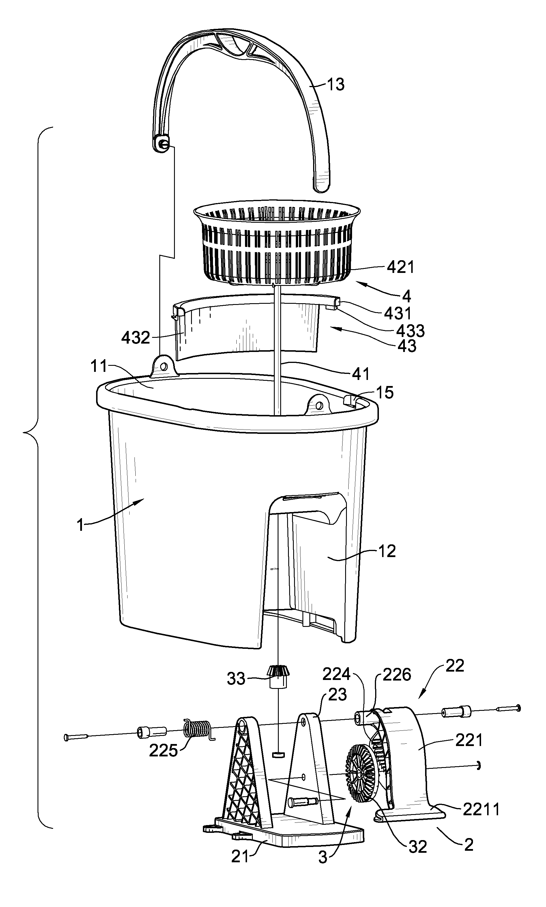
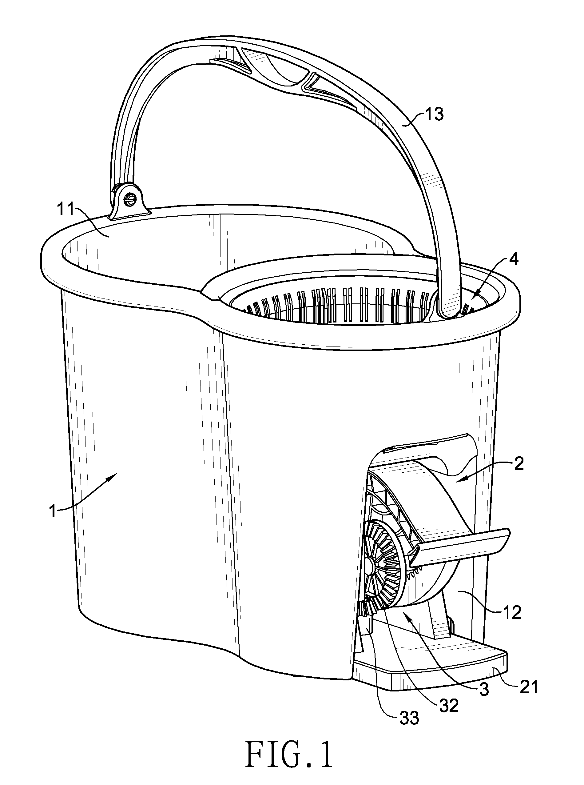
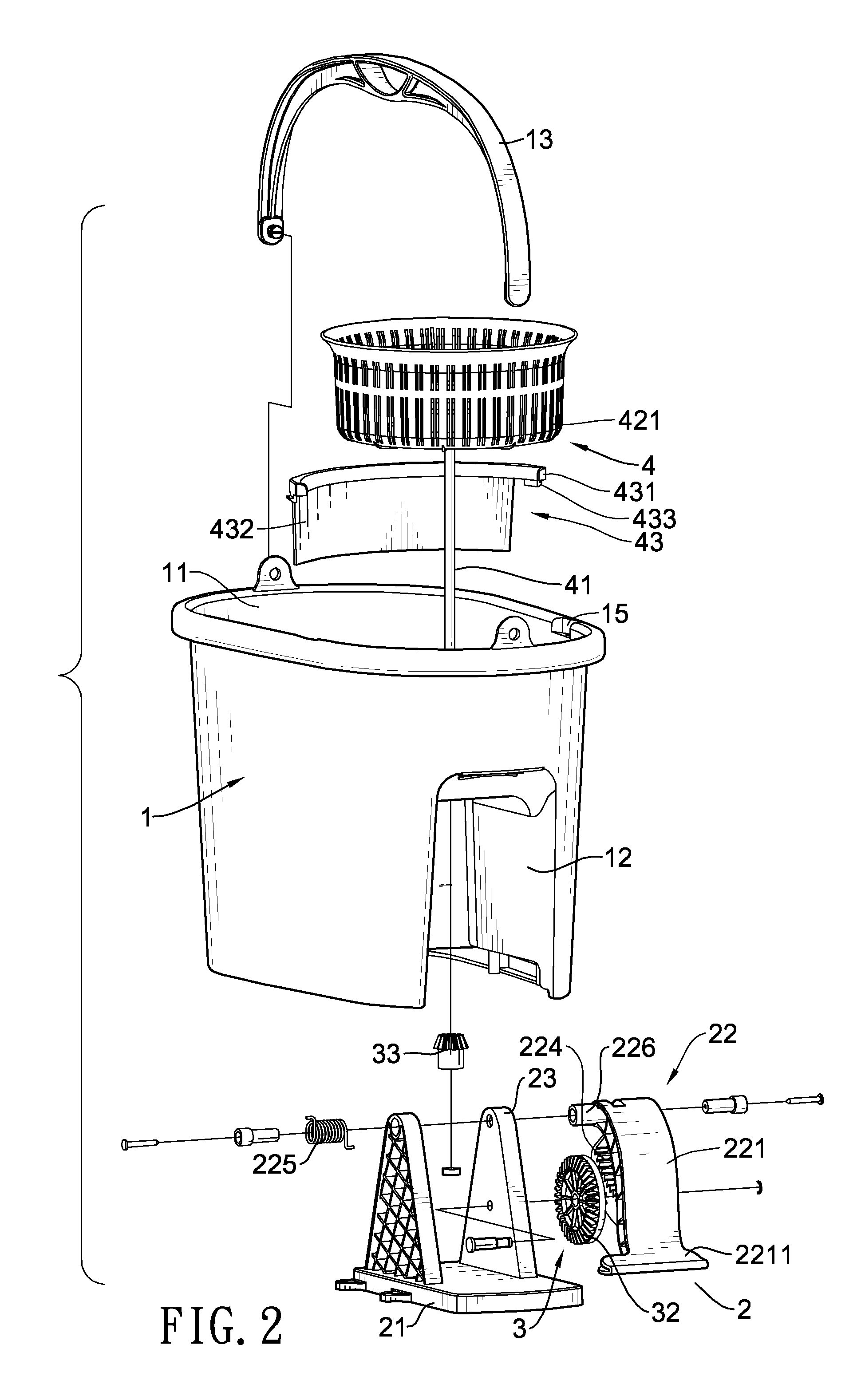
[0022]With reference to FIGS. 1 to 3, a mop strainer of the present invention has a bucket (1), a driving unit (2), a transmission unit (3) and a draining unit (4).

[0023]The bucket (1) is used to contain the water drained from a mop and has a chamber (11), a pedal mount (12), a handle (13), a bottom board (14) and two recesses (15).

[0024]The chamber (11) is defined in the bucket (1) and serves to accommodate water. The pedal mount (12) is a recess formed into the bucket (1) for receiving the driving unit (2), the transmission unit (3) and a part of the draining unit (4). The handle (13) has two ends pivotally mounted on a top edge of the bucket (1) for lifting the bucket (1). The bottom board (14) is a bottom of the bucket (1) and has an uneven portion (141) and a raised portion (142). With reference to FIG. 6, the raised portion (142) is raised above the uneven portion (141) and is located directly above the pedal mount (12). Multiple parallel ribs (143) are formed on the uneven po...


PUM

PropertyMeasurementUnit
heightsaaaaaaaaaa
strengthaaaaaaaaaa
stepping pressureaaaaaaaaaa

Abstract

A mop strainer has a bucket, a driving unit, a transmission unit and a draining unit. The driving unit and the transmission unit are received in a pedal mount of the mop strainer. The driving unit and the transmission unit are driven by stepping on the driving unit, so as to rotate the draining unit and drain a mop. The driving unit has a reinforced sector wall and a limit slot to limit the stroke in operation. The draining unit has a water guard to prevent drained water from sputtering out and the water guard further has a mop gripper for holding the mop. Given all these features, the present invention is more robust and can be operated and stored more conveniently and practically.

Description

BACKGROUND OF THE INVENTION[0001]1. Field of the Invention[0002]The present invention is related to a mop strainer, and more particularly to a mop strainer extracting water with centrifugal force.[0003]2. Description of the Related Art[0004]Draining a mop is a painstaking job. If a mop is not fully drained, a floor mopped thereby could be left wet and slippery. People walking on a wet floor may easily slip and fall, sometimes, such risk may be life-threatening.[0005]To improve draining efficiency, a conventional pail for a mop has a bucket, a driving unit, a transmission unit and a draining unit. The bucket has a chamber for receiving the driving unit. The driving unit has a base fixedly mounted on the bucket. A movable member pivotally reciprocating and a transmission member controlled by the movable member are mounted on the base. A pedal is formed on one side of the movable member for a user to step on. An arced rack is stretched over a rear surface of the pedal, and a free end o...

Claims


Application Information

Patent Timeline
Patent Type & Authority Patents(United States)
IPC IPC(8): A47L13/58
CPCA47L13/58A47L13/59
Inventor LIN, CHING-CHUN
Owner LIN CHING CHUN
Why Eureka
Try Eureka