Extendable helical antenna for personal communication device

Active Publication Date: 2009-09-08
MOBIT TELECOM
View PDF6 Cites 23 Cited by
  • Summary
  • Abstract
  • Description
  • Claims
  • Application Information

AI Technical Summary

Benefits of technology

[0036]It is another object of the present invention to provide a device and method for collocating two antennas in a small v

Problems solved by technology

Ideally, a small and efficient antenna should be designed for most wireless devices, however, a well known rule of thumb trades off between these two parameters, limiting the miniaturization of the electrical size of an antenna, for a given efficiency.
Clearly, smaller than λ/4 antennas can be tuned for a specific frequency, yet this usually degrades the antenna efficiency.
Thus, an efficient antenna for a relatively low frequency (i.e. long wavelength) is not easily achieved in small dimensions.
Practically, in mobile or portable communication devices, this limitation is particularly relevant to UHF, VHF and lower frequency bands.
The size issue becomes much more challenging when two or more antennas are required to be placed in the same communication device.
Then, each of the antennas has its size reduction limitations, as discussed above, but also, the electromagnetic coupling between the antennas is important, as one antenna might load and reduce the performance of another, if collocated too close.
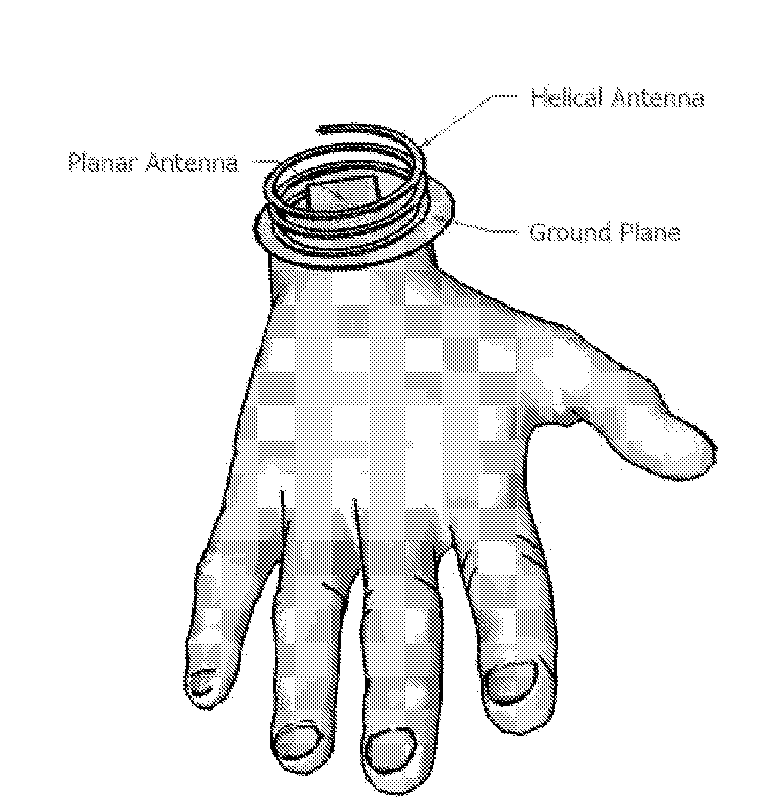
Clearly, holding an operating PLB, with its antenna extended and kept substantially vertically to enable good transmission conditions, might well disturb a person in distress.
Yet, fitting a proper antenna to a wrist-worn PLB is not easy, due to the electrical size of a 406 MHz antenna and considering the interfering of the human body to RF radiation.
Fast detection and location of such accidents is crucial, since survival time in water is limited, typically less than 2 days at ˜20° C. and less than 6 hours at ˜10° C.
Present devices usually operate o

Method used


Image

  • Extendable helical antenna for personal communication device
  • Extendable helical antenna for personal communication device
  • Extendable helical antenna for personal communication device

Examples


Example

[0075]The present invention discloses a personal communication device comprising at least a helical antenna placed over a ground plane, packaged in a case with a rigid cover, said helical antenna axis substantially perpendicular to said ground plane and said helical antenna base substantially close to said ground plane, said ground plane size at least of a circle having a diameter not less than the helical antenna base diameter, said helical antenna made of an elastic conductive spring configured to change its height along its axis, at least: a) pressed down between said case and said cover achieving a low profile; or b) extended to a higher height improving antenna gain upon removing said cover, wherein the antenna is extended upon removing said cover only by means of its own spring force, and wherein the extended helical antenna radius is either constant or decreases as the distance from the ground plane increases.

[0076]FIG. 1 show a cylindrical helical antennas in two different p...


PUM


Abstract

The present invention discloses a portable personal communication device with an extendable helical antenna. This helical antenna is made of an elastic conductive spring, configured to change its height over a ground plane and along the antenna axis, mainly having two positions: a stowed position where the antenna is pressed down between the ground plane and a rigid cover, achieving a low profile; and an operational position where the rigid cover is removed and the antenna is extended by its own spring force, to a higher height, improving antenna gain. Normally, a second planar antenna may be placed over the same ground plane, not exceeding the footprint of the helical antenna, thus utilizing a compactly small volume and yet achieving a considerable electromagnetic decoupling between the antennas, due to their different radiation patterns. According to one embodiment, these antennas are installed in a Personal Locator Beacon (PLB) for Search and Rescue (SAR) of people in distress, where the planar antenna is coupled to a Global Navigation Satellite System (GNSS, such as GPS) receiver, and the helical antenna is coupled to a VHF/UHF radio.

Description

BACKGROUND OF THE INVENTION[0001]Efficiency of an antenna is usually defined as the ratio between the power the antenna radiates and the power put into the antenna by a coupled transmitter. Obviously, a high efficiency is usually desirable in an antenna.[0002]The physical size of an antenna, normalized to its operating wavelength, is usually referred in the art as the “electrical size” of the antenna, so a “small antenna” usually means an Electrically Small Antenna (ESA). Clearly, small antennas are desirable, particularly in mobile device.[0003]In addition, embedding an antenna in a substrate obtaining a dielectric constant larger than 1 (which is the dielectric constant in free space, and approximately the dielectric constant in air), can reduce the antenna size, for a given efficiency, by the square root of the substrate dielectric constant. Yet, in the present document, a dielectric constant of 1 is assumed, unless specified otherwise.[0004]Ideally, a small and efficient antenna...

Claims


Application Information

Patent Timeline
IPC IPC(8): H01Q1/50H01Q1/12
CPCH01Q1/08H01Q1/273H01Q1/362H01Q25/00H01Q9/0407H01Q21/28H01Q1/42
Inventor KATZ
Owner MOBIT TELECOM
Why Eureka
Try Eureka