Furcation bodies and fiber optic assemblies using the same

a technology of fiber optic cables and furcation bodies, which is applied in the direction of optics, fibre mechanical structures, instruments, etc., can solve the problems of cumbersome and/or time-consuming assembly, inability to perform the furcation process in time, and inability to achieve the effect of fast and easy attachment to the fiber optic cable and robust structur

Active Publication Date: 2010-04-27
CORNING OPTICAL COMM LLC
View PDF24 Cites 23 Cited by
  • Summary
  • Abstract
  • Description
  • Claims
  • Application Information

AI Technical Summary

Benefits of technology

[0008]The present disclosure is directed to a furcation body and furcation assemblies for furcating a fiber optic cable. The furcation body includes a channel forming a passageway extending from a front end to a back end of the furcation body. The furcation body also has one or more attachment grooves suitable for securing the furcation body to a portion of the fiber optic cable and the back section of channel sized for receiving a furcation tube. The furcation body may be attached to the fiber optic cable quickly and easily without the use of tools, adhesive, or the like while still providing a robust structure. However, the craft may optionally crimp and / or use an adhesive to attach the furcation body to the fiber optic cable.

Problems solved by technology

Performing the furcation process can take a great deal of time because each optical fiber in a drop cable is usually manually routed and / or furcated and then individually connected to other optical fibers.
Furcating drop cables is required because the desired connectors may not be designed to be installed on large, rigid, outdoor-rated drop cables.
While these products provide some protection for the coated fiber as it enters the connector, the transition from the drop cable to the tube (which typically has 1 millimeter outside diameter (OD)) is not particularly robust.
Moreover, the assembly can be cumbersome and / or time-consuming to assemble in the field.

Method used


Image

  • Furcation bodies and fiber optic assemblies using the same
  • Furcation bodies and fiber optic assemblies using the same
  • Furcation bodies and fiber optic assemblies using the same

Examples


Embodiment Construction

[0026]Reference is now made to preferred embodiments, examples of which are illustrated in the accompanying drawings. Whenever possible, the same or similar reference numbers and symbols are used throughout the drawings to refer to the same or similar parts.

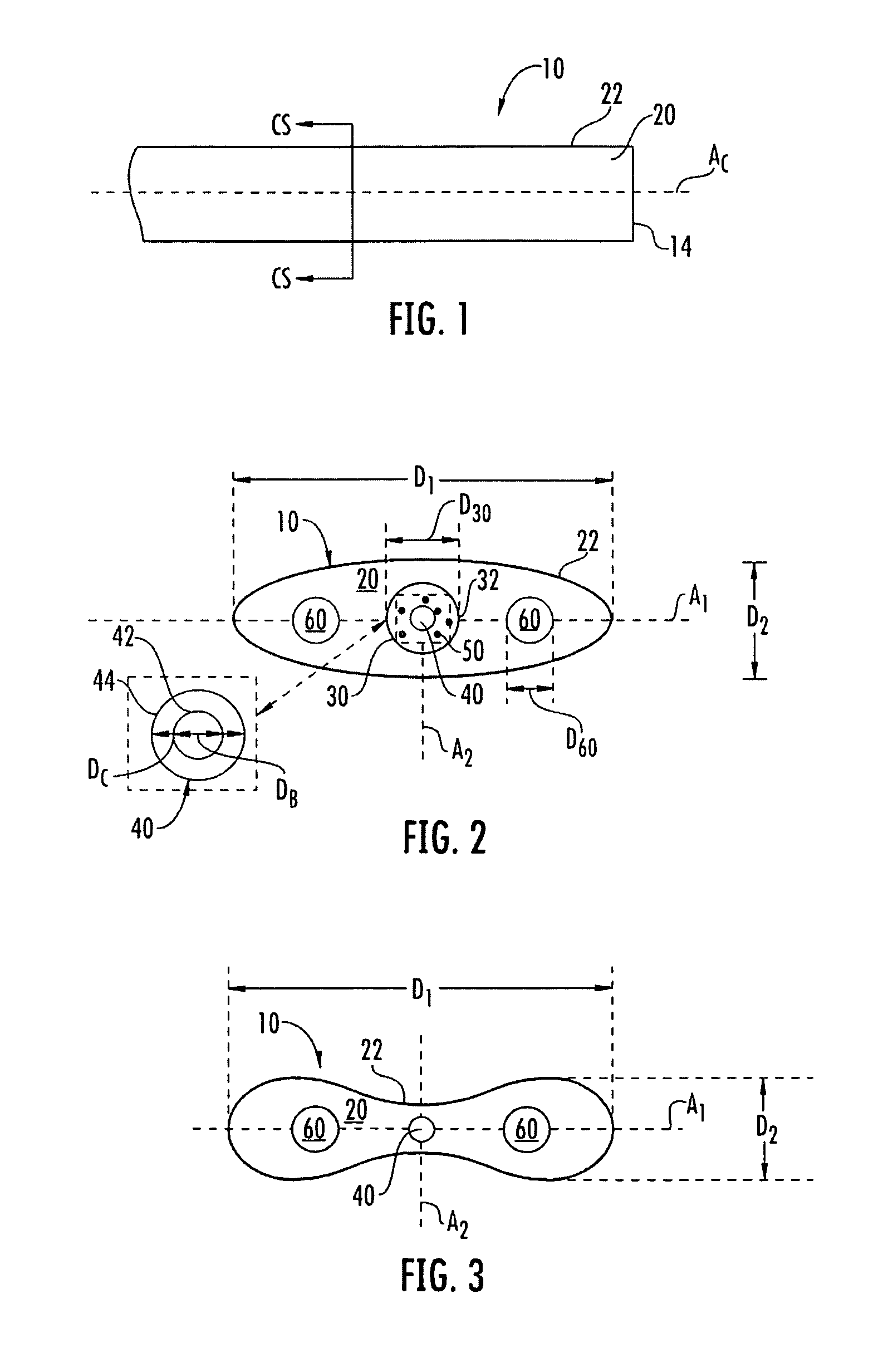
[0027]FIG. 1 is a schematic side view of a generic fiber optic drop cable (“drop cable”) 10 of the type that is portion of the furcation assemblies as described below. Drop cable 10 includes an end 14, a central axis AC, and a cable jacket 20 that defines an outer surface 22 of the fiber optic cable. In an example embodiment, cable jacket 20 is made from polyethylene (PE), but other suitable polymers and / or blends of polymers are possible. Moreover, cable jacket 20 can have any suitable shape and / or size for use with the furcation bodies disclosed.

[0028]While a various types of fiber optic drop cables 10 exist, they can be divided into two main categories: buffered and unbuffered. A buffered fiber optic drop cable carries at leas...


PUM


Abstract

Furcation bodies and furcation assemblies are disclosed. In one embodiment, a furcation body includes a channel forming a passageway extending from the front end to a back end of the furcation body. The furcation body may accommodate different styles and / or sizes of fiber optic cables. For instance, the furcation body may be secured to either a buffer tube of a buffered drop cable or a cable jacket of an unbuffered drop cable. Additionally, assemblies may include a furcation tube secured to the furcation member back end for protecting the optical fiber extending from the furcation body and / or a fiber optic connector. Furcation assemblies having multiple fibers are also disclosed.

Description

BACKGROUND[0001]1. Field[0002]The present disclosure relates generally to furcation bodies for fiber optic cables. More specifically, the disclosure relates to furcation bodies, associated fiber optic cable assemblies having furcation bodies along with methods therefor.[0003]2. Technical Background[0004]Fiber optic communications has experienced explosive growth. In just a few years, the transmission of communication signals for voice, video, data, and the like has soared. Moreover, future growth is planned as fiber optic communication technology improves and networks expand to provide greater access to subscribers.[0005]Fiber optic cables are the backbone of fiber optic communication systems. Fiber optic cables carry optical fibers and other cable elements, which are protected from the external environment by a cable jacket. However, there are several different types of fiber optic cables available for routing optical fibers toward the subscriber. The optical fibers of the fiber op...

Claims


Application Information

Patent Timeline
Patent Type & Authority Patents(United States)
IPC IPC(8): G02B6/36
CPCG02B6/4471G02B6/4473
Inventor DE JONG, MICHAELDEVEREAUX, PAUL X.VO, CHANH C.
Owner CORNING OPTICAL COMM LLC
Why Eureka
Try Eureka