Bag with caster wheels

a caster wheel and bag technology, applied in the direction of folding cycles, cycles, trolleys/perambulators with multiple axes, etc., can solve the problems of increased manufacturing costs, difficult to reinforce, complex structure of main bags, etc., and achieve mass production at low cost, simple structure, and robust structure

Inactive Publication Date: 2007-08-07
SWANY
View PDF22 Cites 20 Cited by
  • Summary
  • Abstract
  • Description
  • Claims
  • Application Information

AI Technical Summary

Benefits of technology

[0010]The bag with this structure has a feature that the inside of the main bag can be made deeper because the telescopic rods are fixed to the side. However, in the bag with this structure, since the telescopic rods are fixed to the main bag, the main bag needs to have a robust structure. This is because the telescopic rods need to stand on their own with the main bag. The bag with this structure is not moved by pulling the telescopic rods as shown in FIG. 1, but the main bag is moved by pushing forward while being used as a stick for a support of a walker, and thus, a robust structure in which even pushing does not allow the bag to fall is required. Accordingly, in order to achieve a structure in which the telescopic rods can stand on their own with the main bag, attaching parts between the main bag and the telescopic rods need to be reinforced robustly. This disadvantageously makes the structure of the main bag complex and remarkably increases manufacturing costs. Also, the main bag has a problem that it is difficult to reinforce it so as to have a robust structure without reducing storage space.
[0013]In the bag with this structure, the main bag is joined to the stand with the reinforcement walls preventing the telescopic rods from falling. However, since the reinforcement walls are provided along both of the end edges of the stand, the main bag needs to be mounted between the reinforcement walls at both of the end edges. This causes a distance between the pair of reinforcement walls to specify a width of the main bag, and if the width of the main bag is increased, the distance between the reinforcement walls needs to be increased, that is, the distance between the telescopic rods needs to be increased. Accordingly, when the reinforcement walls spaced widely are mounted on the base frame, the distance between the telescopic rods becomes larger, and thus, the grip becomes longer.
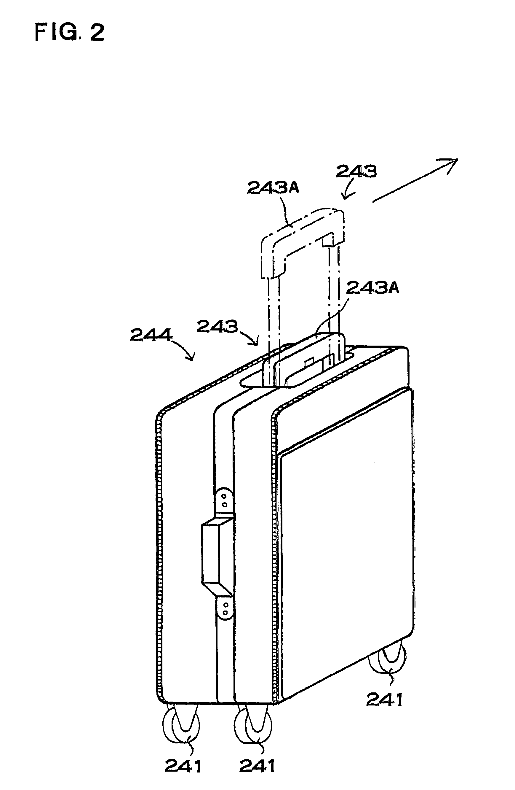
[0014]As the grip becomes longer, a weight of the whole bag is increased. Furthermore, a joining rod 57 joining the telescopic rods 55, or the like becomes longer, and thus the weight is further increased. The bag in which the telescopic rods 55 are provided at both of the end edges of the stand 52, as shown in FIG. 5, is suitable to a structure in which the main bag 53 is mounted on the stand 52 in a vertically standing position. However, in this structure, when the main bag 53 is mounted on the stand 52 in the vertical position, the distance between the telescopic rods becomes extremely large, and the grip 54 becomes very long.
[0016]The invention has been further developed in order to solve the above-described problem. An important object of the invention is to provide a bag with caster wheels in which telescopic rods provided in the middle of a stand can be securely joined to the stand with a robust structure.
[0017]Another important object of the invention is to provide a bag with caster wheels in which a main bag has a simple structure and the bag can be mass-produced at low cost, and in addition, the telescopic rods stably stand on their own, so that the bag can be easily moved forward by gripping a grip part at the upper ends of the telescopic rods.
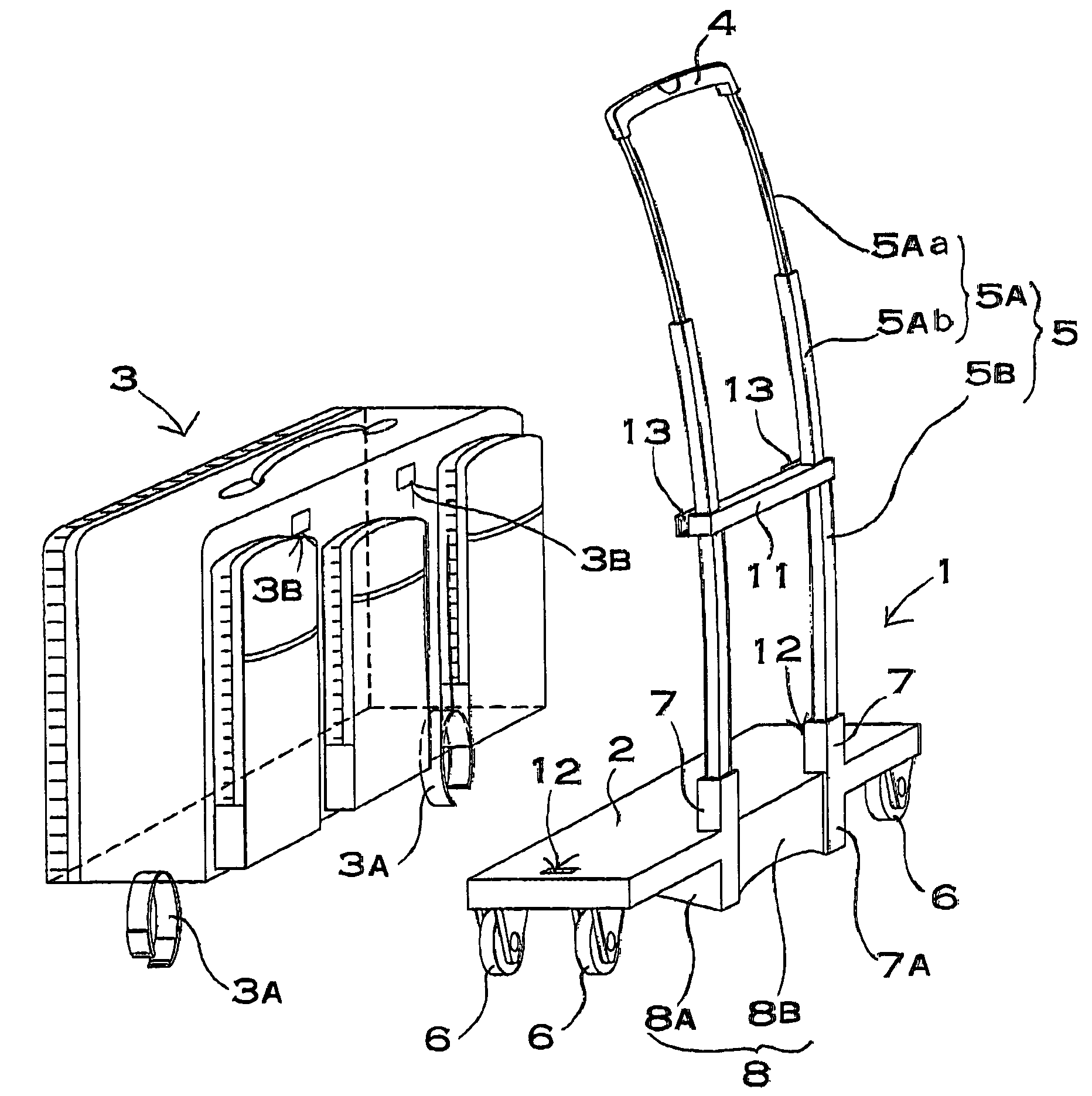
[0019]The above-described bag with caster wheels has a feature that the telescopic rods provided in the middle of the stand can be securely joined to the stand with a robust structure. This is because in the bag with caster wheels of the invention, the supporting cylinders into which the telescopic rods are inserted to be joined are provided in the stand, and these supporting cylinders are arranged between the caster wheels provided at the four corners of the stand and are projected in the lower surface of the stand, and further, the reinforcement walls in the position oriented in the lateral direction of the stand are provided in the lower surface projection parts of the supporting cylinders, so that the supporting cylinders are supported by these reinforcement walls. In this bag with this structure, since the supporting cylinders are projected in the lower surface of the stand and the reinforcement walls are joined to these projected parts to support the supporting cylinders instead of providing the reinforcement walls in the upper surface of the stand to join the supporting cylinders, the telescopic rods provided in the middle of the stand can be securely joined to the stand with the robust structure, while the main bag can be ideally arranged without limiting the upper surface of the stand. Also, the bag with this structure has features that it allows the telescopic rods to stably stand on their own and allows the user to move forward while holding the grip part on the upper ends of the telescopic rods, and additionally, that the main bag has a simple structure and thus, low-cost mass production can be achieved.

Problems solved by technology

This disadvantageously makes the structure of the main bag complex and remarkably increases manufacturing costs.
Also, the main bag has a problem that it is difficult to reinforce it so as to have a robust structure without reducing storage space.

Method used


Image

  • Bag with caster wheels
  • Bag with caster wheels
  • Bag with caster wheels

Examples


Embodiment Construction

[0048]A bag with caster wheels shown in FIGS. 6 to 8 includes the base frame 1 provided with caster wheels 6 which are free to swivel in any direction, at four corner regions of a bottom surface thereof, and the main bag 3 mounted on this base frame 1. In the bag in the figures, the main bag 3 is detachably mounted on the base frame 1. This bag has a feature that the main bag 3 can be easily replaced. However, the main bag can also be undetachably fixed to the base frame.

[0049]The base frame 1 is manufactured by forming plastic. The base frame 1, as shown in FIG. 7 and FIGS. 9 to 11, includes the stand 2 provided with the cater wheels 6 at the four corner regions and mounting the main bag 3 thereon, the telescopic rods 5 which are fixed on one side of this stand 2 so as to elongate upward and stand on their own, and which can be freely extracted upward and has the grip 4 at upper ends thereof, and stoppers for stopping the telescopic rods 5 at an extension position and at a retracti...


PUM


Abstract

A bag with caster wheels includes a base frame 1 having caster wheels 6 and a main bag 3. The base frame 1 includes a stand 2 mounting the main bag 3 thereon and telescopic rods 5 joined on one side of this stand 2 or between both sides. The stand 2 includes supporting cylinders 7 into which the telescopic rods 5 are inserted to be joined. The supporting cylinders 7 are arranged between the caster wheels 6 provided at four corners of the stand 2, and are projected in a lower surface of the stand 2, so that a projection height (d) thereof is made lower than a height (h) of the caster wheels 6. In lower surface projected parts 7A of the supporting cylinders 7, reinforcement walls 8 joined to the lower surface of the stand 2 are provided. The reinforcement walls 8 are arranged between the caster wheels 6 and in a posture oriented in a lateral direction of the stand 2. In this bag, the supporting cylinders 7 are joined to the stand 2 while being reinforced by the reinforcement walls 8, and lower ends of the telescopic rods 5 are joined to these supporting cylinders 7.

Description

BACKGROUND OF THE INVENTION[0001]1. Field of the Invention[0002]The invention relates to a bag with caster wheels, and in particular to a bag having a vertically movable handle.[0003]2. Description of the Related Art[0004]Bags with caster wheels each having an extractive handle have been developed and widely used. Many types of the bags with this structure are each small enough to carry it on an airplane or a little larger than this. The bags with this structure are described in the specification of U.S. Pat. No. 4,995,487, Japanese Examined Patent Publication No. 4-76686, Japanese Unexamined Utility Model Publication No. 57-179824, and Japanese Unexamined Utility Model Publication No. 63-131634. The bags described in these publications are each provided with two caster wheels 41 on one side of a bottom surface as shown in FIG. 1. On the opposite side of the caster wheels 41, short legs 42 are fixed. When the bag is in a vertically standing position, the caster wheels 41 and the leg...

Claims


Application Information

Patent Timeline
Patent Type & Authority Patents(United States)
IPC IPC(8): B62D33/08B62B3/00
CPCA45C5/14A45C13/385B62B1/125B62B2202/24
Inventor MIYOSHI, ETSUO
Owner SWANY
Why Eureka
Try Eureka