Compact LED package with reduced field angle

a technology of led package and field angle, which is applied in the direction of instrumentation, lighting and heating apparatus, planar/plate-like light guides, etc., can solve the problems of increased height and size, unsatisfactory dome shape, and increased height and siz

Inactive Publication Date: 2006-12-21
AVAGO TECH ECBU IP (SINGAPORE) PTE LTD
View PDF4 Cites 49 Cited by
  • Summary
  • Abstract
  • Description
  • Claims
  • Application Information

AI Technical Summary

Problems solved by technology

Current problems include an undesirable dome shape caused by an optical lens since a flat-sided and oblong shape is preferred for manufacturability and pick-and-place setups.
Additionally, use of an optical lens adds height and size to the overall package thickness.
Increased height and size are marked problems for big chip LED's, for example, a 1 watt LED of 0.9 mm×0.9 mm, as big chip LED's require big lenses to collimate the emitted light for increased brightness.
Similarly, in a smaller LED package of 1-2 mm but with space restraints on the packaging, an LED with a lens presents design problems due to the lens height.

Method used


Image

  • Compact LED package with reduced field angle
  • Compact LED package with reduced field angle
  • Compact LED package with reduced field angle

Examples


Embodiment Construction

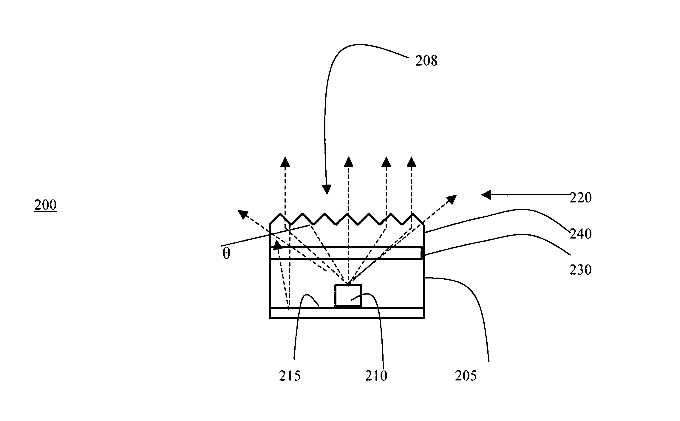
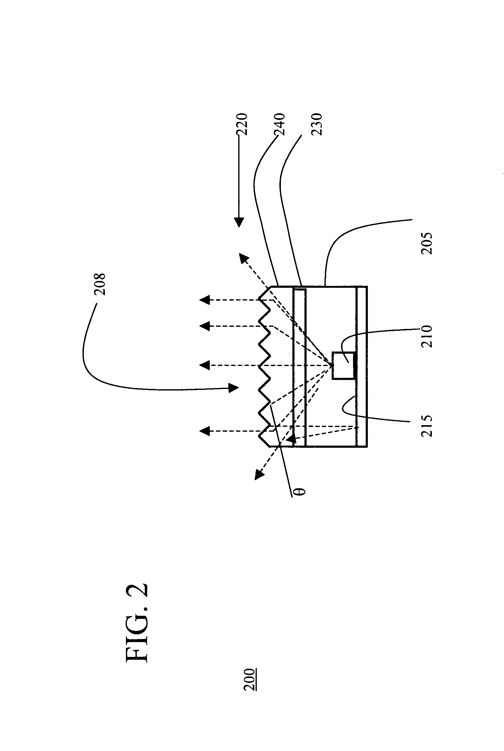
[0018]FIG. 2 illustrates one embodiment of a light emitting diode lighting system 200 in accordance with one aspect of the invention. Light emitting diode lighting system 200 includes housing 205, light emitting diode 210 and base 215. Housing 205 includes a light emission opening 208 configured to allow light emitted by light emitting diode 205 to radiate from within housing 205. Housing 205 surrounds light emitting diode 210, such that light emitting diode 210 is disposed within housing 205.

[0019] In one embodiment, base 215 includes a mirror-finish layer attached to the housing 205, such that light emitting diode 210 rests upon the mirror-finish layer. A mirror-finish layer is any reflective surface, such as a mirror or other similarly reflective surface. In one embodiment, the mirror-finish layer includes a grooved surface configured to direct incoming light toward a first and second film layer 230, 240 covering the light emission opening 208.

[0020] Light emitting diode 210 em...


PUM


Abstract

A light emitting diode system includes a housing including a light emission opening and a light emitting diode disposed within the housing. A first film layer covers the light emission opening and includes a uniaxial collimating film configured to direct light from the light emitting diode along a first axis.

Description

BACKGROUND OF THE INVENTION [0001] Current Light Emitting Diode (“LED”) packages have a general wide or narrow field of view (“FOV”). To achieve this currently, a lens is used to collimate the light from the light source / die. This normally adds additional height and area to the LED package. Current problems include an undesirable dome shape caused by an optical lens since a flat-sided and oblong shape is preferred for manufacturability and pick-and-place setups. Additionally, use of an optical lens adds height and size to the overall package thickness. [0002]FIGS. 1A, 1B, and 1C illustrate prior art methods of collimating LED light. As shown in FIG. 1A, LED light source 101 emits light beams 105 through lens 110. Similarly, FIG. 1B illustrates light source 101 emitting light beams 105 through another lens 110 and reflecting light beams 105 off reflector cup 115. Likewise, FIG. 1C illustrates LED light source 101 emitting light beams 105 through a lens 110 and reflected by reflector ...

Claims


Application Information

Patent Timeline
Patent Type & Authority Applications(United States)
IPC IPC(8): F21V7/00H01L33/58
CPCG02B5/045H01L33/58G02B6/4206F21V5/02F21V13/04G02B6/0011
Inventor GOON, WOOI KINMOK, THYE LINNNG, KEE YEANCHUA, BEE YIN JANETCHEW, GIM ENGHELBING, RENE P.
Owner AVAGO TECH ECBU IP (SINGAPORE) PTE LTD
Why Eureka
Try Eureka