
Tourniquet cuff with improved pneumatic passageway

a technology of tourniquet cuff and pneumatic passageway, which is applied in the field of pneumatic tourniquet cuff, can solve the problems of ineffective audio-visual, ineffectiveness of audio-visual, and complete obstruction of the pneumatic passageway within the prior art tourniquet cu

Inactive Publication Date: 2006-12-21
WESTERN CLINICAL ENG
View PDF35 Cites 79 Cited by
  • Summary
  • Abstract
  • Description
  • Claims
  • Application Information

AI Technical Summary

Problems solved by technology

One hazard associated with all pneumatic tourniquet cuffs of the prior art is the obstruction of the pneumatic passageway within the cuff.
Any isolated region may be hazardous, either by permitting arterial blood to flow into the limb past a region of lower cuff pressure or by requiring surgical staff to set the tourniquet instrument to an unnecessarily high pressure to stop blood flow past the cuff.
Also, any complete obstruction of the pneumatic passageway within a tourniquet cuff of the prior art may render ineffective any audio-visual safety alarms of a connected prior-art tourniquet instrument intended to warn of hazardous over-pressurization or under-pressurization of the cuff, such as the safety alarms described by McEwen in U.S. Pat. No. 4,469,099.
Another hazard associated with tourniquet cuffs of the prior art is partial obstruction of the pneumatic passageway.
A partial obstruction of the pneumatic passageway at the port connector, or elsewhere within the port or inflatable portion of a prior-art cuff may increase the pneumatic flow resistance at the partial obstruction, and thus may affect the ability of a connected tourniquet instrument to rapidly and accurately regulate pressure past the partial obstruction and throughout the inflatable portion of the tourniquet cuff.
Increased flow resistance from a partial obstruction may also reduce the ability of a connected tourniquet instrument to accurately and rapidly indicate changes of the pressure in the tourniquet cuff to surgical staff.
Further, a partial obstruction of the pneumatic passageway within a region of the inflatable portion of the cuff may affect the ability of the tourniquet instrument to uniformly regulate pressure throughout the entire inflatable portion of the cuff.
In addition to the hazards of complete and partial obstructions that may affect the integrity of the pneumatic passageway, another hazard associated with prior-art cuffs is the interruption of the passageway due to unanticipated detachment of the port connector from the tourniquet instrument, or detachment of the port connector from the port, thus separating the inflatable portion of the tourniquet cuff from the tourniquet instrument.
A related hazard is a leak at the port connector that is sufficiently large to prevent a connected tourniquet instrument from maintaining cuff pressure near the desired pressure.
Such a large leak may result, for example, from deterioration or deformation of the connector of a single-use disposable tourniquet cuff as a result of reprocessing and reuse of the disposable tourniquet cuff in multiple surgical procedures in a manner neither intended nor anticipated by the manufacturer.
Although such-long and flexible port tubing facilitates connection of the port to non-sterile instrument tubing away from the sterile surgical field, it may also increase the possibility of partial or complete obstruction of the pneumatic passageway within the port, for example by accidental kinking, bending, or pinching of the tubing.
Reprocessing, cleaning and re-sterilizing of disposable tourniquet cuffs may result in hazards for the surgical patients on whom such cuffs are subsequently used.
The hazard arises from the use of any of a variety of chemical or physical agents that are attendant with the reprocessing, cleaning or re-sterilizing processes.
Exposure of prior-art cuffs to sterilizing agents different than the sterilizing agent employed at the time of manufacture may produce a change and deterioration in the properties of some cuff materials and components, for example due to a chemical reaction or exposure to radiation.
Exposure of a prior-art cuff containing flexible thermoplastic materials to an elevated temperature during cleaning or sterilization by known prior-art processes may soften thermoplastic materials and components, increasing the likelihood of hazardous deformation of some components.
For example, an elevated temperature during reprocessing may result in substantial deformation of the thermoplastic stiffener included in some prior-art cuffs, thus impairing the application of pressure by such a cuff to an underlying limb upon subsequent use in surgery.
Also, an elevated temperature during reprocessing may deform the thermoplastic connectors of some prior-art cuffs, or may weaken the retention force of typical thermoplastic barb-type port connectors, so that such connectors cannot establish or reliably maintain a gas-tight passageway between the tourniquet cuff and tourniquet instrument upon reuse.
An elevated temperature associated with cleaning or re-sterilization increases the likelihood that the pneumatic passageway within the cuff may become partially or completely obstructed, as described above, as a result of such reprocessing.
Repeated cleaning, re-sterilization and reuse of a disposable tourniquet cuff in multiple surgical procedures may progressively increase the hazard for the surgical patients on whom the cuff is used.

Method used


Image

  • Tourniquet cuff with improved pneumatic passageway
  • Tourniquet cuff with improved pneumatic passageway
  • Tourniquet cuff with improved pneumatic passageway

Examples


Embodiment Construction

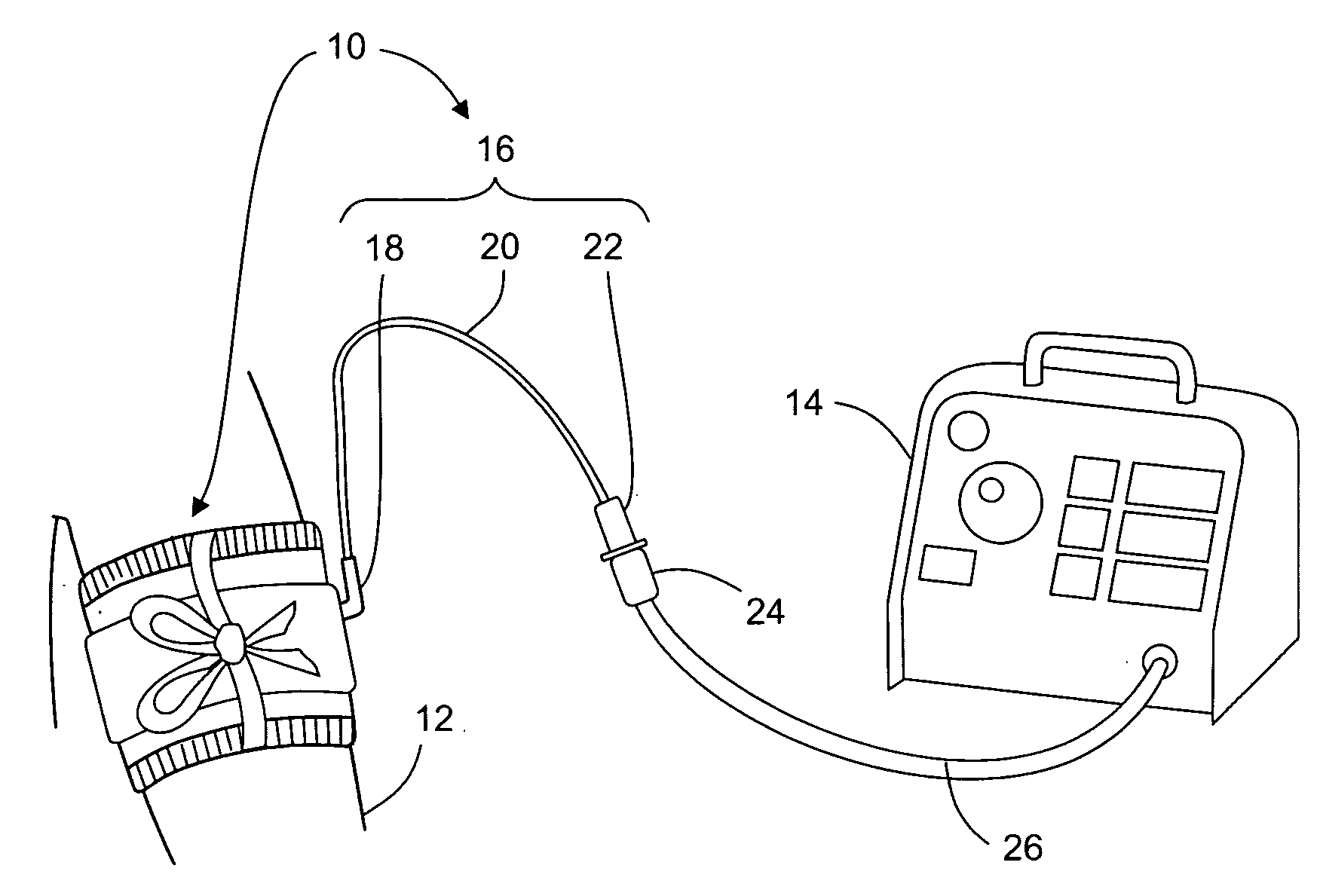
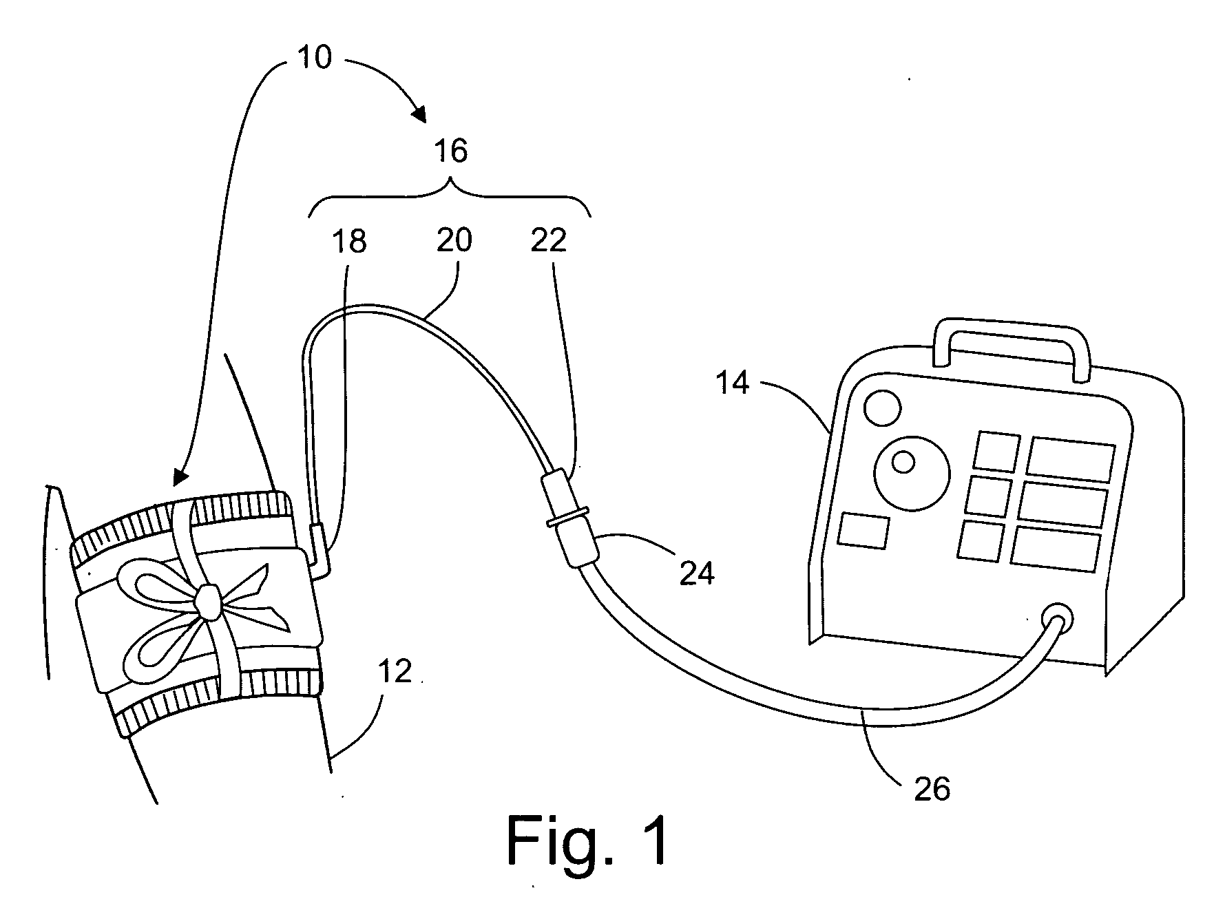
[0022]FIG. 1 is a pictorial representation of the preferred embodiment in a surgical application, showing the tourniquet cuff 10 applied to patient limb 12 and pneumatically connectable to tourniquet instrument 14. Cuff 10 includes cuff port 16, which comprises bladder sealing flange 18, port tubing 20, and port connector 22. In the preferred embodiment shown, cuff 10 is a single port cuff, where cuff port 16 provides a single pneumatic passageway to the inflatable portion of cuff 10. Those skilled in the art will appreciate that the features described in the preferred embodiment may also be applied to tourniquet cuffs having more than one port, such as those described by U.S. Pat. No. 4,469,099, U.S. Pat. No. 4,479,494, and U.S. Pat. No. 5,254,087. Cuff port 16 is pneumatically connected to tourniquet instrument 14 via instrument connector 24 and instrument tubing 26. In the preferred embodiment cuff port 16 is of sufficient length to allow pneumatic connection between cuff 10 and ...


PUM


Abstract

A tourniquet cuff has minimal flow restrictions within its pneumatic passageway under normal operating conditions, has a substantially reduced likelihood of partial or complete obstructions or interruptions of the pneumatic passageway under foreseeable operating conditions, can indicate exposure of the cuff to external agents that are capable of affecting the integrity of the pneumatic passageway before use, and can be manufactured economically.

Description

FIELD OF THE INVENTION [0001] This invention pertains to pneumatic tourniquet cuffs commonly used for stopping arterial blood flow into a portion of a surgical patient's limb to facilitate the performance of a surgical procedure, and for facilitating intravenous regional anesthesia. BACKGROUND OF THE INVENTION [0002] A typical surgical tourniquet system of the prior art includes a tourniquet cuff for encircling a patient's limb at a desired location and a tourniquet instrument that includes flexible instrument tubing for connecting to the tourniquet cuff. The tourniquet cuff typically includes an inflatable portion, and the inflatable portion of the cuff is typically connected through a cuff port having a port connector to the flexible instrument tubing of the tourniquet instrument, thereby establishing a pneumatic passageway from the tourniquet instrument through the instrument tubing and the cuff port into the inflatable portion of the cuff. In some prior-art systems, the tourniqu...

Claims


Application Information

Patent Timeline
Patent Type & Authority Applications(United States)
IPC IPC(8): A61B17/00
CPCA61B17/135A61B2019/4836A61B2017/00955A61B2090/0807
Inventor MCEWEN, JAMES A.GLINZ, KENNETH L.INKPEN, KEVIN B.JAMESON, MICHAEL
Owner WESTERN CLINICAL ENG
Learn More