Resilient clip fastener

a technology of resilient clip and fastener, which is applied in the direction of threaded fasteners, pedestrian/occupant safety arrangements, vehicular safety arrangements, etc., can solve the problems of significant increase in the required insertion force, the fastener may not be properly seated and secured to the sheet metal, and the condition is particularly problemati

Inactive Publication Date: 2006-12-28
NEWFREY
View PDF3 Cites 1 Cited by
  • Summary
  • Abstract
  • Description
  • Claims
  • Application Information

AI Technical Summary

Benefits of technology

[0007] Accordingly, there remains a need in the art for an improved fastener having a relatively low installation force and a relatively high removal force that is relatively more tolerant of misalignment problems. Ideally, the fastener should be inexpensive to manufacture, reliable and simple to install. Furthermore, the fastener should be particularly adapted for securing structures to one another in a manner which minimizes vibration and the concomitant noise problems that are often associated with such fasteners. SUMMARY

Problems solved by technology

Due to slight misalignments which can occur between the fasteners and their corresponding mounting holes, some of the fasteners may not be properly seated and secured to the sheet metal.
This condition is especially problematic when dealing with the fasteners that serve to anchor the roof mounted assist handles.
Because these fasteners must withstand substantially higher removal forces than the fasteners that serve merely to hold the headliner in place, they are typically less forgiving of misalignment problems, which can result in a significant increase in the required insertion force, thus greatly increasing the likelihood of improper installation.
Under the circumstances, the removal forces that the fasteners can withstand before separating from the sheet metal are greatly compromised.

Method used


Image

  • Resilient clip fastener
  • Resilient clip fastener
  • Resilient clip fastener

Examples


Embodiment Construction

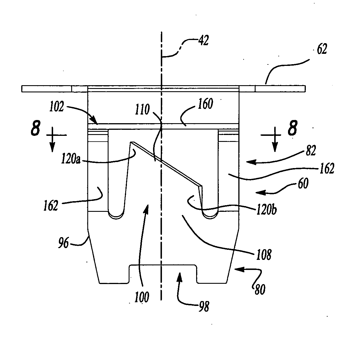
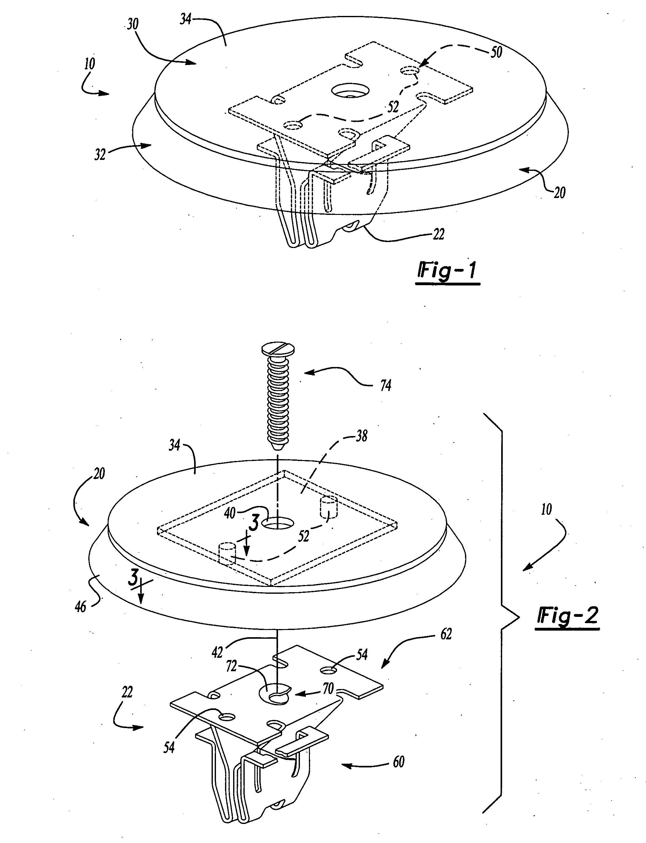
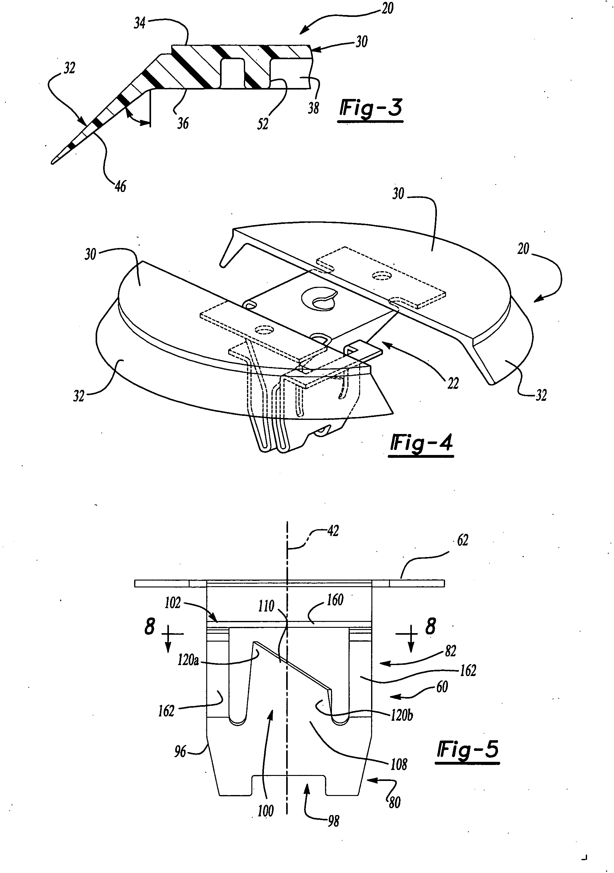
[0036] With reference to FIGS. 1 and 2 of the drawings, a resilient clip fastener constructed in accordance with the teachings of a first embodiment of the present disclosure is generally indicated by reference numeral 10. Fastener 10 is illustrated to include a spacing structure 20 and a clip structure 22. Spacing structure 20 is preferably unitarily formed from a resilient material, such as plastic, with materials such as polypropylene being particularly well suited for automotive applications. Spacing structure 20 is shown to include a first flange member 30 and a second flange member 32. With additional reference to FIG. 3, the outer surface 34 of the first flange member 30 is substantially flat while the inner surface 36 of the first flange member 30 includes a recess 38. A mounting hole 40 is formed through the center of the first flange member 30 along a central axis 42 of the fastener 10.

[0037] In the particular embodiment illustrated, the first flange member 30 is circular...


PUM


Abstract

A resilient clip with a plurality of twisted wings for engaging a first structure. The twisted wings provide the clip with a low ratio of insertion force to pull-out force, rendering the clip relatively easy to install yet difficult to pull out. In one embodiment, the resilient clip includes at least three wing members that cooperate to prevent the resilient clip from rotating relative to the first structure. In another embodiment, the resilient clip includes an engagement portion having a plurality of teeth for engaging a tab formed into a second structure. The teeth of the engagement portion engage the tab, permitting the resilient clip to be coupled to the second structure. When the resilient clip is engaged to the first structure, the teeth of the engagement portion cannot disengage the tab, rendering the resilient clip non-removably coupling the resilient clip to the first and second structures.

Description

CROSS-REFERENCE TO RELATED APPLICATIONS [0001] This application is a continuation of co-pending U.S. application Ser. No. 09 / 813,592, filed Mar. 21, 2001, which is a continuation-in-part of U.S. application Ser. No. 09 / 772,046, filed Jan. 29, 2001, which claims the benefit of U.S. Provisional Application Ser. No. 60 / 192,375 filed Mar. 27, 2000 entitled “Fastener Assembly for Automotive Headliner”.INTRODUCTION [0002] The present disclosure relates generally to resilient clip fasteners and more particularly to a resilient clip fastener that employs a plurality of wing members to secure the body portion of the resilient clip to a structure. More specifically, the present disclosure relates to a resilient clip fastener having a construction that utilizes wing member to permits the clip to be inserted with a relatively low insertion force while resisting relatively high withdrawal forces. The disclosure also relates to a resilient clip fastener having a construction that accounts in seve...

Claims


Application Information

Patent Timeline
Patent Type & Authority Applications(United States)
IPC IPC(8): E04F19/02A44B99/00B60N3/02B60R13/02B60R21/205F16B37/02F16B37/04
CPCB60N3/026B60R13/0206B60R13/0212B60R13/0256Y10T24/307B60R2013/0287F16B37/02F16B37/043Y10T24/304B60R21/205
Inventor LUBERA, DANIEL J.SIUDYM, JACOB A. IIOSTERLAND, ROBERT
Owner NEWFREY
Why Eureka
Try Eureka