Variable response time transient partial flow sampling system and method

a sampling system and partial flow technology, applied in the field of variable response time transient partial flow sampling system and method, can solve the problems of less than satisfactory data, difficult to correct the time lag, and preclude the use of existing full dilution tunnels for off-highway developmen

Active Publication Date: 2006-12-28
CATERPILLAR INC
View PDF5 Cites 10 Cited by
  • Summary
  • Abstract
  • Description
  • Claims
  • Application Information

AI Technical Summary

Problems solved by technology

Furthermore, the sheer number of off-highway ratings to be developed, in combination with concurrent regulatory pressure placed on-highway engine development times, nearly precludes the use of existing full dilution tunnels for off-highway development, even for small engines.
For instance, if the controller commands a change to the sampling system too quickly after an air or fuel supply change has occurred, the exhaust may be over or under sampled for a brief duration, resulting in less than satisfactory data.
Correctly adjusting for this time lag can be even more difficult if the sampling system is to be made more versatile and useful with a variety of different sized engines.
These devices are large, expensive, difficult to maintain and are engine size specific.
However, the current versions do not address applications where the engine size is very small relative to the volume of the exhaust system upstream from the partial flow system sample probe location, or in cases where exhaust after treatment research requires that a significant exhaust system volume be located between the engine and the partial flow system sample probe location.

Method used


Image

  • Variable response time transient partial flow sampling system and method
  • Variable response time transient partial flow sampling system and method
  • Variable response time transient partial flow sampling system and method

Examples


Embodiment Construction

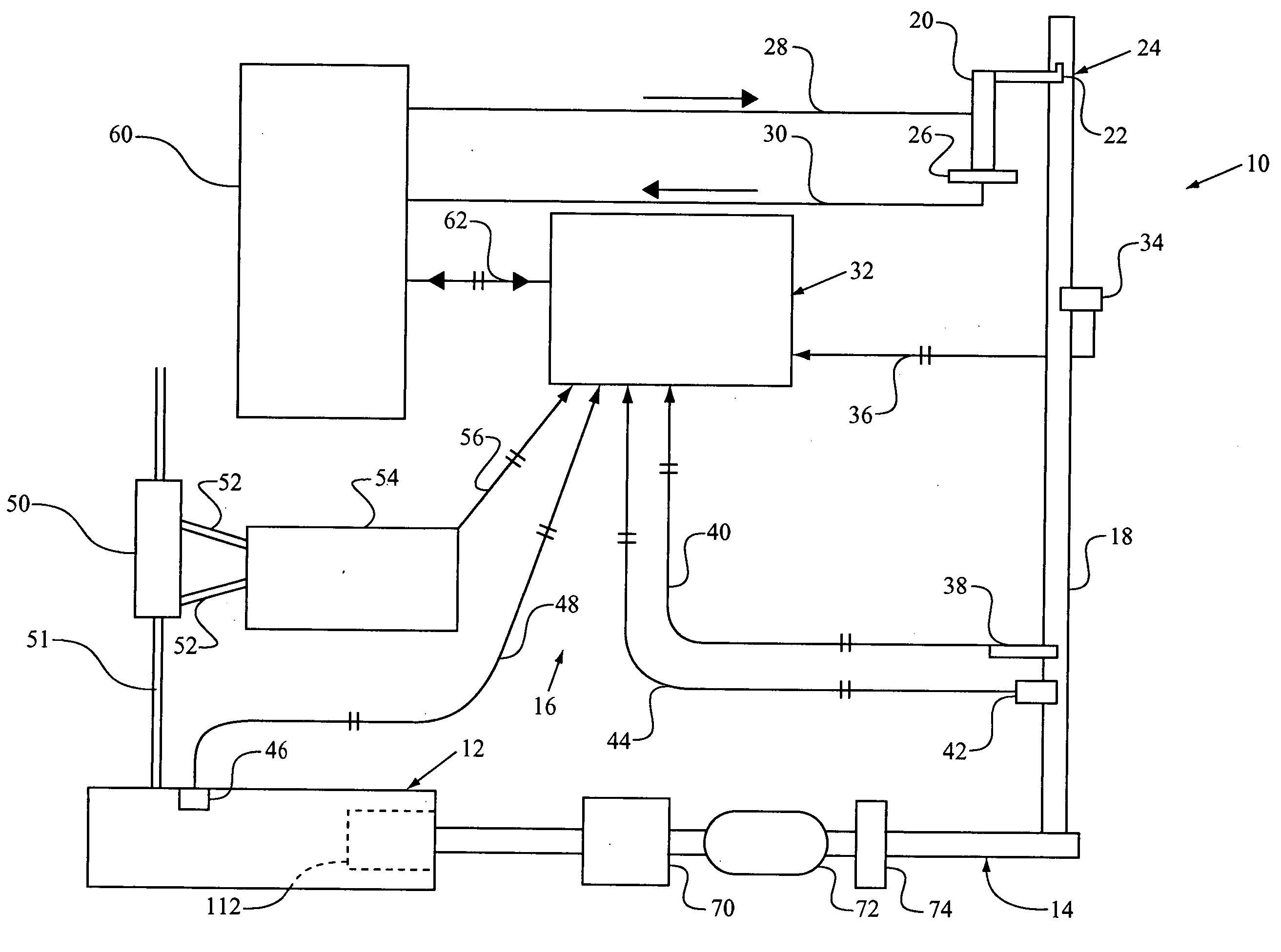
[0011] Referring to FIG. 1, a test set up 10 includes an engine 12 attached to an exhaust stack 14 and a gas sampling system 16. Set up 10 can accommodate either a relatively large engine 12 or a relatively small engine 112, and provide accurate test results for either. The sampling system 16 includes a computer 32 in communication with a variety of known gas sampling system components 60 and a dilution tunnel 20 that includes a probe 22 positioned at a location 24 in an exhaust stack section 18 of exhaust stack 14. The gas sampling system operates in a conventional manner but is controlled by computer 32 such that a controlled flow rate of dilution air is provided from system components 60 via dilution air supply line 28 to the dilution tunnel assembly 20, in a known manner. A portion of the exhaust gas and any suspended particulate matter are drawn into dilution tunnel 20 via probe 22. At that point, the exhaust and the dilution air are combined, passed through a filter 26, and th...


PUM

PropertyMeasurementUnit
temperatureaaaaaaaaaa
time delayaaaaaaaaaa
air dilution flow rateaaaaaaaaaa

Abstract

A partial flow dilution tunnel in a gas sampling system is connected to the exhaust from an internal combustion engine. More accurate gas sampling results are enabled for accounting for a delay from when the engine produces an exhaust change to when that transient arrives at a probe location. Thus, an estimated time delay is determined, and the gas sampling system is operated at least in part based upon that estimated time delay for the exhaust to arrive at the sampling location.

Description

TECHNICAL FIELD [0001] The present disclosure relates generally to the sampling of combustion products for testing, and more particularly to a method of operating a partial flow dilution tunnel in a gas sampling system for testing exhaust from an internal combustion engine. BACKGROUND [0002] Exhaust gas sampling systems that utilize partial flow dilution tunnels (PFDT) have been used since the early 1990s as an effective alternative to full dilution tunnel systems for development and certification of engines where steady state model testing was permitted. Previously, all off-highway and until recently much of European bound on-highway engine testing and certification was performed with systems utilizing PFDT's, due to the fact that they are more portable, less expensive and often more repeatable than their full dilution counterparts. Regulatory organizations such as ISO, CARB, EPA and EEC all permit the use of PFDT's for steady state test cycle certification. One such system is disc...

Claims


Application Information

Patent Timeline
Patent Type & Authority Applications(United States)
IPC IPC(8): G01N7/00
CPCG01N2001/2264G01N1/2252
Inventor GRAZE, RUSSELL R. JR.
Owner CATERPILLAR INC
Why Eureka
Try Eureka