Belt conveyor and image forming apparatus using the same

a technology of image forming apparatus and belt conveyor, which is applied in the direction of electrographic process apparatus, instruments, optics, etc., can solve the problems of color image position offset, color misregistration, high degree of accuracy, etc., and achieve high image quality, high accuracy, and prevent the effect of belt fractur

Inactive Publication Date: 2006-12-28
RICOH KK
View PDF4 Cites 47 Cited by
  • Summary
  • Abstract
  • Description
  • Claims
  • Application Information

AI Technical Summary

Benefits of technology

[0030] According to the above configuration, the position of the endless belt in the width direction can be detected over a wide range with high accuracy, and meandering of the endless belt is corrected in accordance with the detection signal, and hence an image forming apparatus which produces a high-quality, high image-quality image can be provided.
[0031] When the amount of displacement of the endless belt exceeds the predetermined range and an anomaly arises, there is also yielded an effect of the belt conveyor being capable of reliably detecting the anomaly and stopping the driving of the endless belt, to thus prevent fracture of the belt.

Problems solved by technology

This meandering phenomenon causes positional offsets of color images and, by extension, color misregistration, when the images of respective colors are transferred onto the intermediate transfer belt in a superposing manner.
One technical problem encountered by the method for controlling the inclination of the meandering correction roller is a method for detecting the amount of meandering of the transfer belt over a wide range and with a high degree of accuracy.
Another problem is to detect an anomaly when the amount of meandering has exceeded a certain range, to thus prevent occurrence of breakage of the belt without fail.
However, according to the above method, the range where movement of the transfer belt can be detected and the detection accuracies are contrary to each other.
The second technical problem is to detect anomalies in meandering of the transfer belt.

Method used


Image

  • Belt conveyor and image forming apparatus using the same
  • Belt conveyor and image forming apparatus using the same
  • Belt conveyor and image forming apparatus using the same

Examples


first embodiment

Belt Conveyor

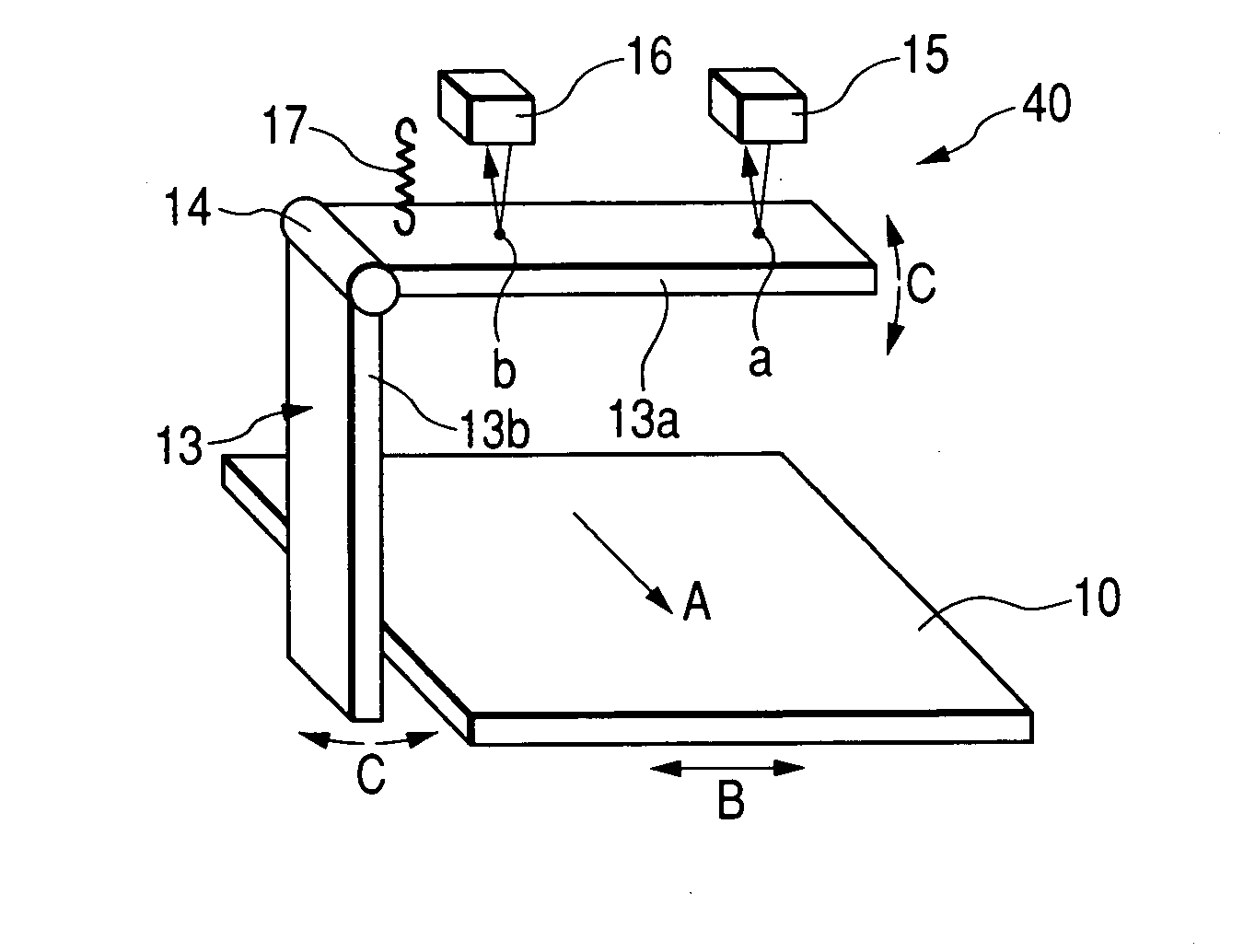
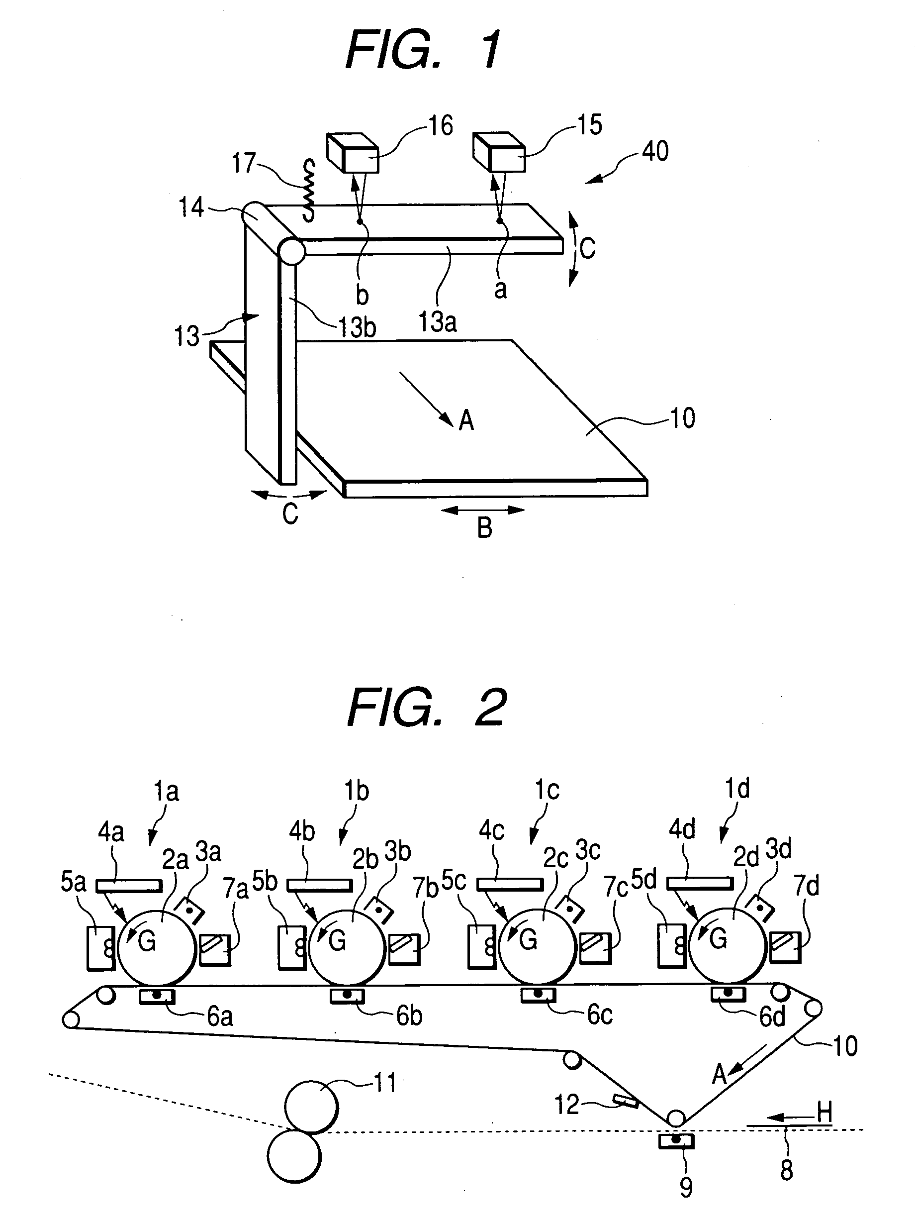
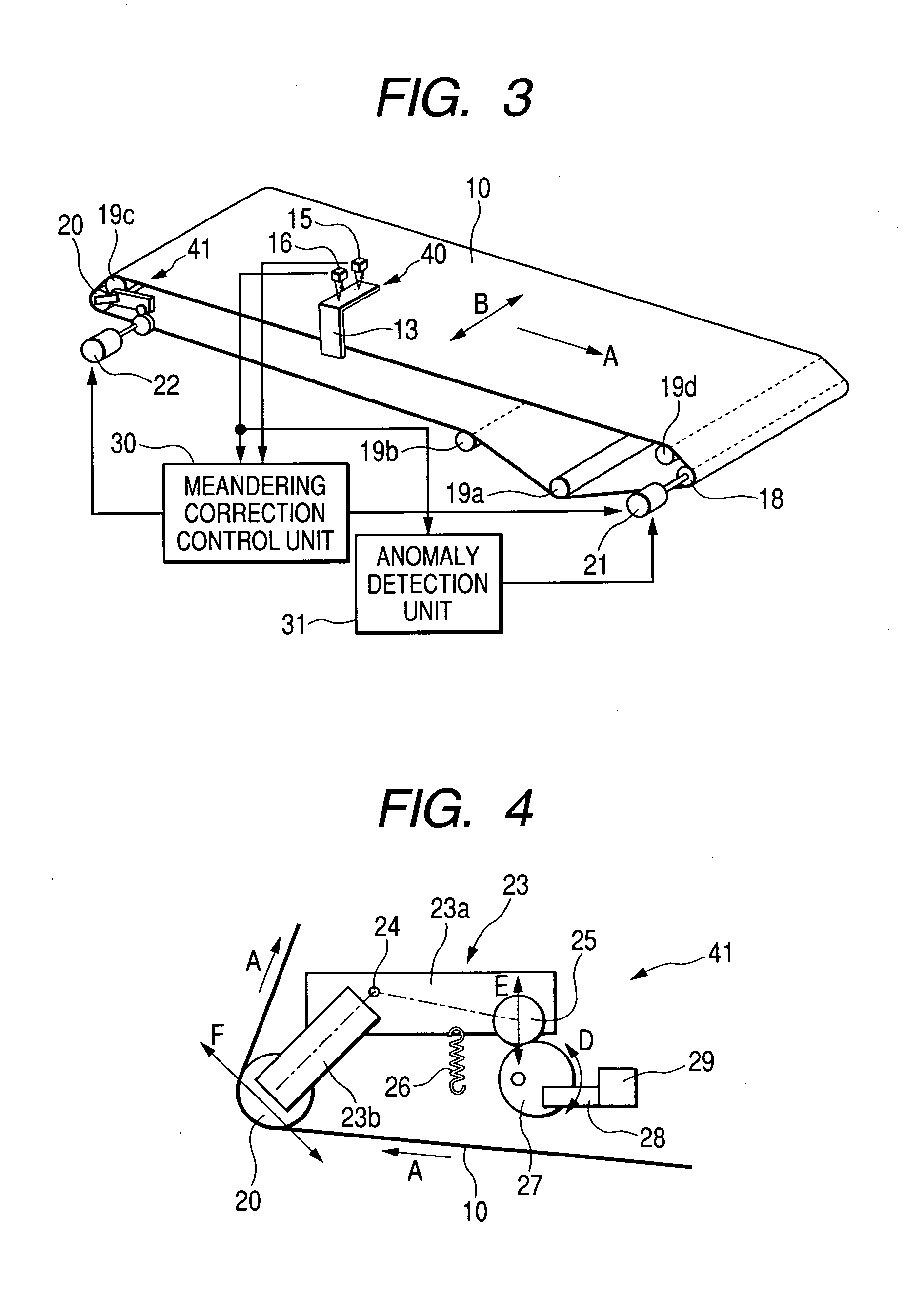
[0061]FIG. 3 is a diagrammatic view of a configuration of a belt conveyor according to a first embodiment of the invention used for driving the endless transfer belt 10. As shown in FIG. 3, the belt conveyor of the present embodiment includes the endless transfer belt 10, a belt position detection mechanism 40, a belt meandering correction mechanism 41, a meandering correction control section 30, an anomaly detection section 31, and the like. The transfer belt 10, which is an endless belt, is looped over a drive roller 18, a meandering correction roller 20, and driven rollers 19a to 19d. The drive roller 18 is coupled to a belt drive motor 21. When the motor 21 is rotated, the belt 10 moves. In the following descriptions, the direction of arrow A in FIG. 3 is called a belt conveying direction, and the direction of arrow B is called a belt width direction.

[0062] The belt position detection mechanism 40 detects the position of the edge of the transfer belt 10, whereby ...

second embodiment

[0097]FIG. 10 is a diagrammatic view showing a belt conveyor according to a second embodiment of the present invention. In the drawing, the belt conveyor is identical with the configuration shown in FIG. 3 except the configuration of the belt position detection mechanism section 40. Explanations about the elements other than the mechanism section 40 are omitted.

[0098] In the first embodiment, two displacement detection sensors are used as the belt position detection unit. One of the two sensors is comparatively, highly accurate because of its detection accuracy of 10 μm, and hence expensive. In the present embodiment, a displacement sensor 35, inferior to detection accuracy to the displacement sensor 16 and having a detection range which is wider than that of the displacement sensor 16 is used. Hence, the belt position detection mechanism 40 will be described hereunder with reference to FIG. 9.

[0099] In FIG. 9, the contact 13 is formed into an L-shaped form from the members 13a, 1...

third embodiment

[0104]FIG. 12 is a diagrammatic view showing a belt conveyor according to a third embodiment of the present invention. The present embodiment is also configured analogously to the embodiment shown in FIG. 3 except the belt position detection mechanism 40.

[0105] The belt position detection mechanism 40 of the present embodiment has the displacement sensor 15 and edge sensors 36a, 36b disposed on both sides of the belt 10 in the width direction. The displacement sensor 15 is provided at a position opposite the member 13a of the L-shaped contact 13. As shown in FIG. 16, each of the edge sensors 36a, 36b may be configured to have a light-emitting section 60 and a light-receiving section 61. The essential requirement for the edge sensor is a mere sensor or detection mechanism, which can detect presence or absence of the side edge of a belt.

[0106] In the present embodiment, the displacement sensor 15 is arranged in the same manner as in the first embodiment in order to detect the positi...


PUM


Abstract

A belt conveyor includes: an endless belt that is looped over a plurality of rollers, the plurality of rollers including a drive roller and a meandering correction roller; a drive unit that rotates the drive roller to drive the endless belt; a meandering correction unit that adjusts an inclination of the meandering correction roller to correct meandering of the endless belt in a width direction thereof; a plurality of position detection units that detect positions of the endless belt in the width direction thereof and output detection signals; and a meandering correction control unit that selectively uses the detection signals from the plurality of detection units to control the meandering correction unit.

Description

BACKGROUND OF THE INVENTION [0001] 1. Field of the Invention [0002] The present invention relates to image forming apparatus, such as a printer, a copier, and the like, particularly to a belt conveyor having the function of correcting meandering of endless belts, such as an intermediate transfer belt, a sheet transfer belt, and the like, and an image forming apparatus using the belt conveyor. [0003] 2. Description of the Related Art [0004] In relation to a multicolor image forming apparatus, such as a full-color printer or a spot-color printer, a tandem-type multicolor image forming apparatus is available. In this system, a plurality of photosensitive drums are arranged along a conveying direction of an intermediate transfer belt, which is an endless belt, and toner of different colors is caused to adhere to electrostatic latent images formed on the respective photosensitive drums, to thus form toner images and sequentially transfer the toner images on the transfer belt. [0005] This...

Claims


Application Information

Patent Timeline
Patent Type & Authority Applications(United States)
IPC IPC(8): B65G39/16
CPCG03G15/1605G03G2215/0129G03G2215/0016G03G2215/00156G03G15/1615
Inventor FURUYA, NOBUYUKISANO, YOSHIHIKO
Owner RICOH KK
Why Eureka
Try Eureka