Networked monitoring system

a monitoring system and network technology, applied in the field of networked monitoring systems, can solve the problems of large size, inconvenient installation, and high installation costs, and achieve the effect of cost effective installation

Inactive Publication Date: 2006-12-28
MOBILE ASPECTS INC
View PDF99 Cites 38 Cited by
  • Summary
  • Abstract
  • Description
  • Claims
  • Application Information

AI Technical Summary

Benefits of technology

[0009] Therefore, it is an object of the present invention to provide a networked monitoring system that overcomes the deficiencies and drawbacks of the prior art in the field of inventory and identification systems. It is another object of the present invention to provide a networked monitoring system that operates on a wireless communication platform. It is a further object of the present invention to provide a networked monitoring system that is a simple and standalone system that operates over a wireless network. It is a still further object of the present invention to provide a networked monitoring system that can be cost effectively installed and, optionally, operate on a single frequency or multiple frequencies, such as in a radio frequency communications operation. It is yet another object of the present invention to provide a networked monitoring system that allows for communication and data transfer functions between multiple reader or monitoring mechanisms.

Problems solved by technology

However, the accuracy of such systems is suspect.
Further, the use of multiple different reader “check points” throughout the system, or use of a large, overall reading system, is often prohibitively expensive to acquire, install and maintain.
Accordingly, in such systems, the cost of installation can easily be as much as or more than the hardware itself.

Method used


Image

  • Networked monitoring system
  • Networked monitoring system
  • Networked monitoring system

Examples


Embodiment Construction

[0028] For purposes of the description hereinafter, the terms “upper”, “lower”, “right”, “left”, “vertical”, “horizontal”, “top”, “bottom”, “lateral”, “longitudinal” and derivatives thereof shall relate to the invention as it is oriented in the drawing figures. However, it is to be understood that the invention may assume various alternative variations and step sequences, except where expressly specified to the contrary. It is also to be understood that the specific devices and processes illustrated in the attached drawings, and described in the following specification, are simply exemplary embodiments of the invention. Hence, specific dimensions and other physical characteristics related to the embodiments disclosed herein are not to be considered as limiting.

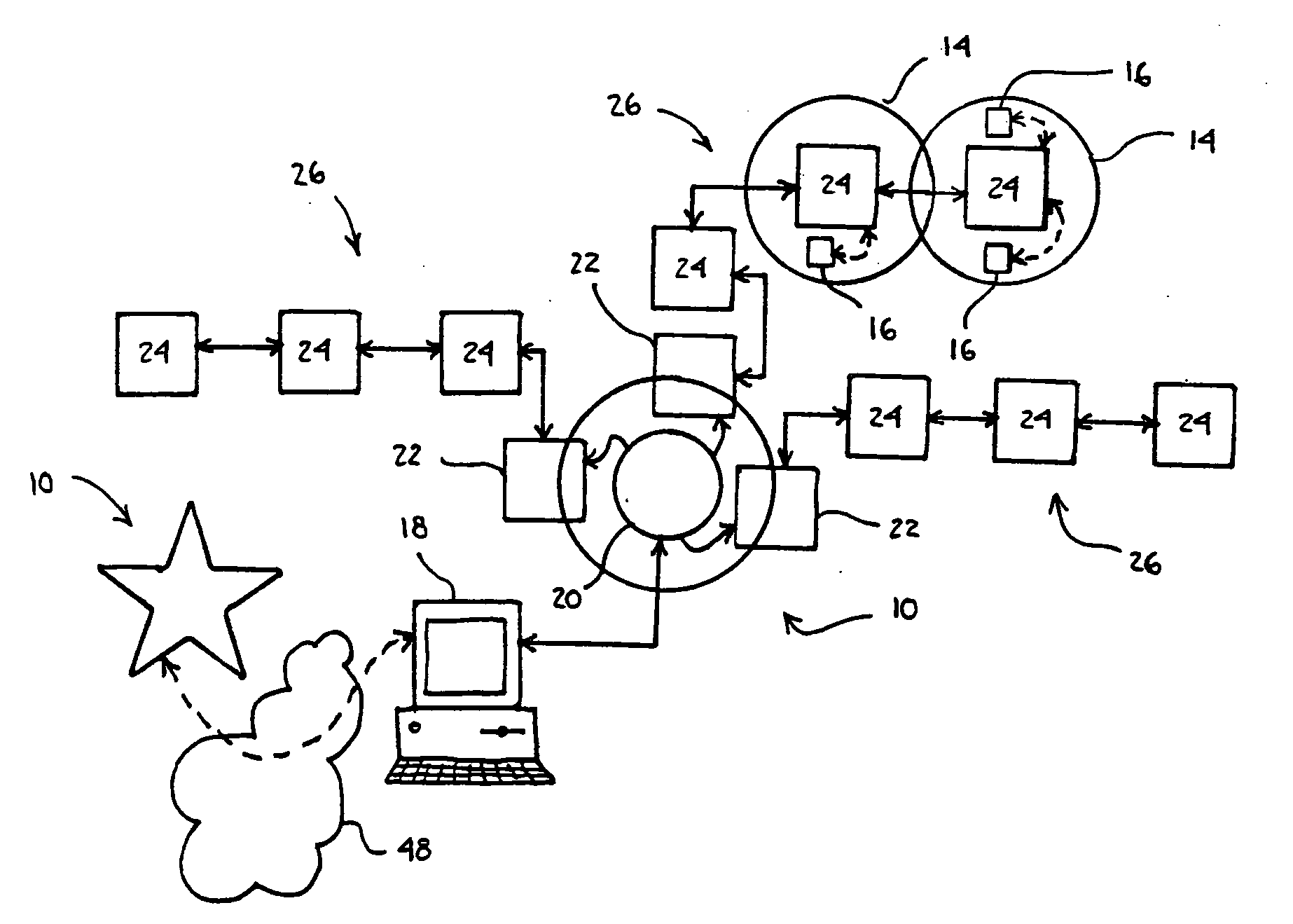
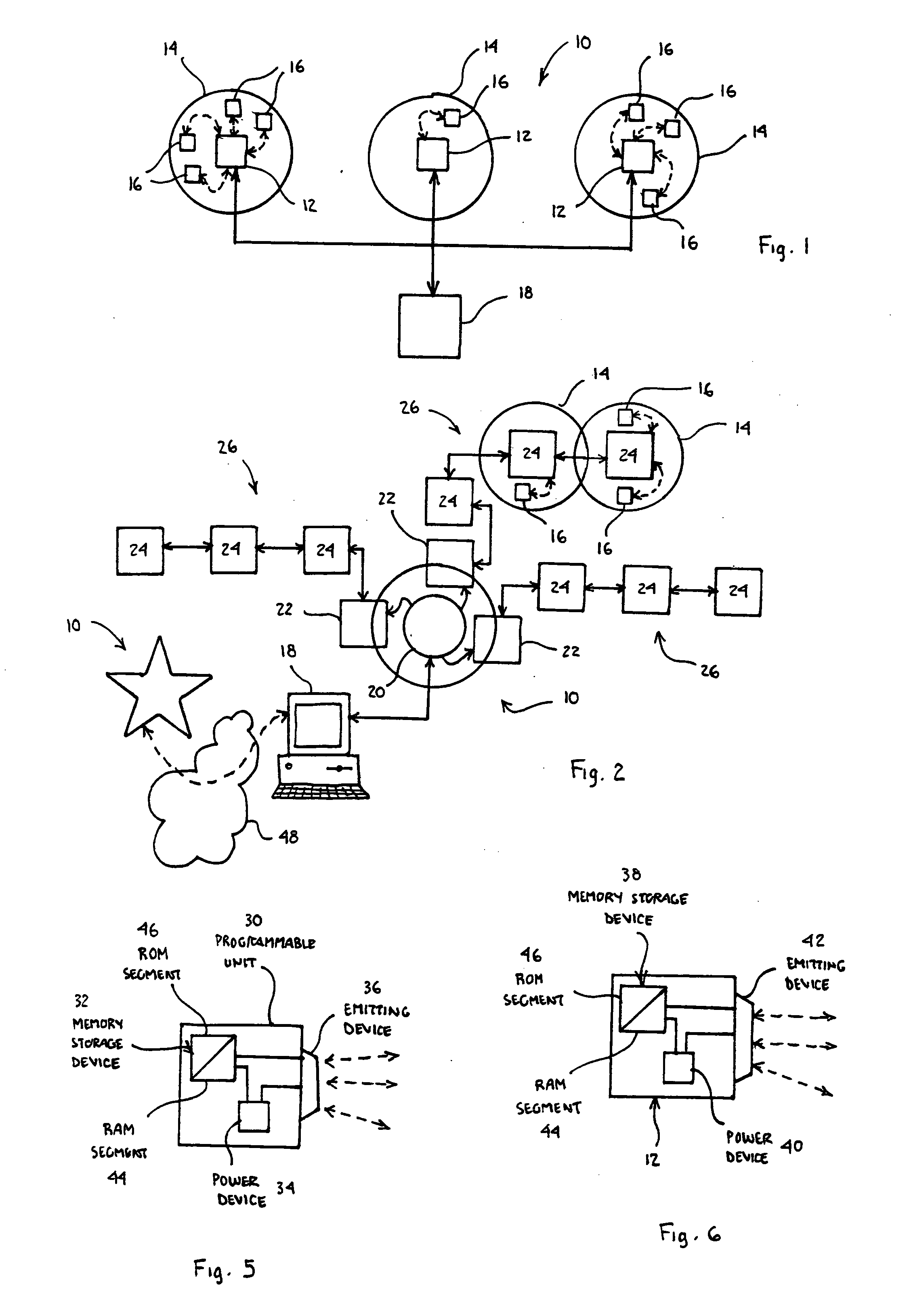
[0029] The present invention is directed to a networked monitoring system 10 for use in a variety of inventory management and asset tracking systems. In one preferred and non-limiting embodiment, the system 10 operates as a r...


PUM


Abstract

A wireless networked monitoring system including multiple reader mechanisms for receiving, processing and transmitting signals, each reader mechanism associated with a read zone. Multiple signal emitting devices or tags are positionable within the read zones and emit signals containing data. A central processing device is in wireless communication with the reader mechanisms and receives, processes and transmits signals. In addition, the central processing device communicates with and controls the reader mechanisms and / or signal emitting devices.

Description

CROSS REFERENCE TO RELATED APPLICATIONS [0001] This application claims priority under 35 U.S.C. § 119(e) from provisional U.S. Patent Application No. 60 / 694,418, filed Jun. 27, 2005, the contents of which are incorporated herein by reference.BACKGROUND OF THE INVENTION [0002] 1. Field of the Invention [0003] The present invention is directed to systems and mechanisms, such as systems for use in identifying items in the field of inventory management and identification technologies and, in particular, to a networked monitoring system operating on a wireless platform, such as in a radio frequency communications system. [0004] 2. Description of Related Art [0005] In many industrial and service applications, a large variety and quantity of items, equipment, persons and objects must be tracked for a variety of reasons. For example, these items may be tracked so that the user knows when additional items should be obtained or ordered, who is using the items and for what purpose, and for exp...

Claims


Application Information

Patent Timeline
Patent Type & Authority Applications(United States)
IPC IPC(8): G06K7/08G06K7/00
CPCG06K2017/0045G06K17/0022
Inventor TAYLOR, CARLSRIHARTO, TIMUR P.
Owner MOBILE ASPECTS INC
Why Eureka
Try Eureka