Supercharge Your Innovation With Domain-Expert AI Agents!

Voltage multiplier circuit including a control circuit providing dynamic output voltage control

a voltage multiplier circuit and control circuit technology, applied in the direction of power conversion systems, instruments, dc-dc conversion, etc., can solve the problem of not wanting voltage variation in the output voltage of the voltage multiplier circui

Active Publication Date: 2006-12-28
MICREL
View PDF3 Cites 15 Cited by
  • Summary
  • Abstract
  • Description
  • Claims
  • Application Information

AI Technical Summary

Benefits of technology

[0007] According to one embodiment of the present invention, a voltage multiplier circuit includes a control circuit and a first voltage multiplier stage. The control circuit has a first input terminal coupled to receive a power supply voltage, a second input terminal coupled to receive a reference voltage. The control circuit provides a first output voltage having a voltage value being the difference between a first selected voltage and the power supply voltage where the first selected voltage is

Problems solved by technology

In some applications, such variations in the voltage multiplier circuit output voltage is not desired, particularly when the voltage multiplier circuit is used to drive MOS devices where precision in the gate drive voltages is critical.

Method used


Image

  • Voltage multiplier circuit including a control circuit providing dynamic output voltage control
  • Voltage multiplier circuit including a control circuit providing dynamic output voltage control
  • Voltage multiplier circuit including a control circuit providing dynamic output voltage control

Examples


Embodiment Construction

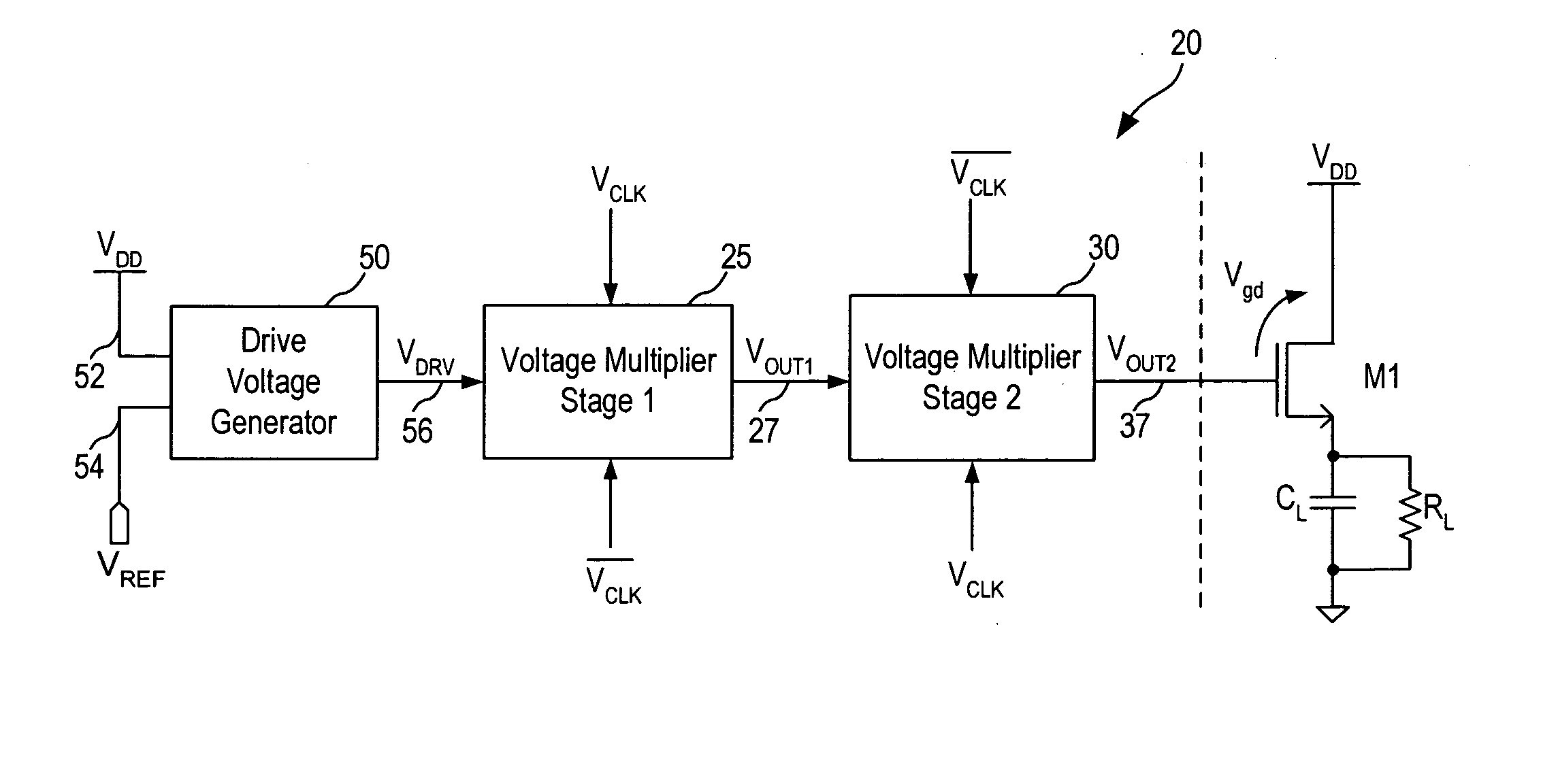
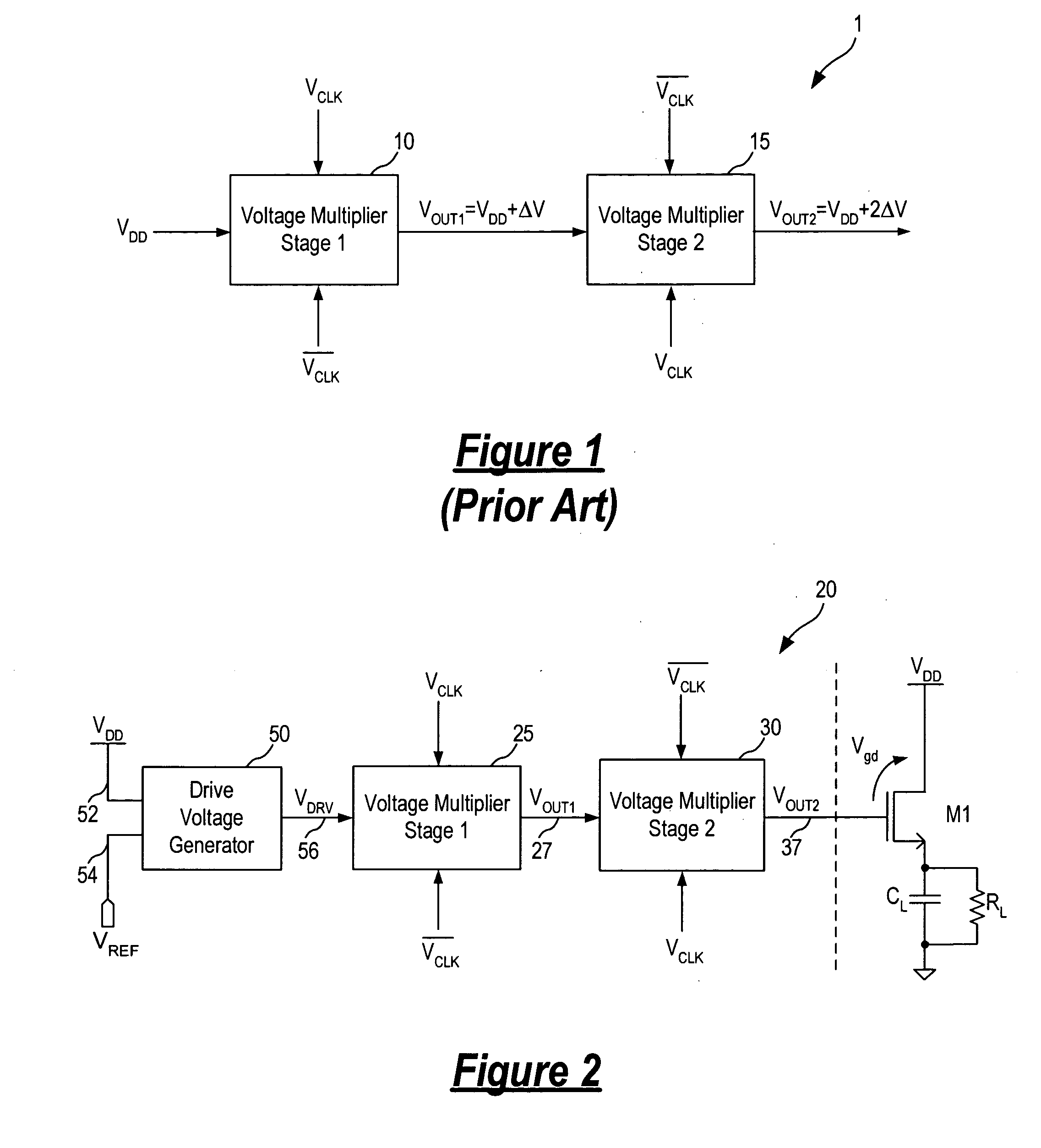
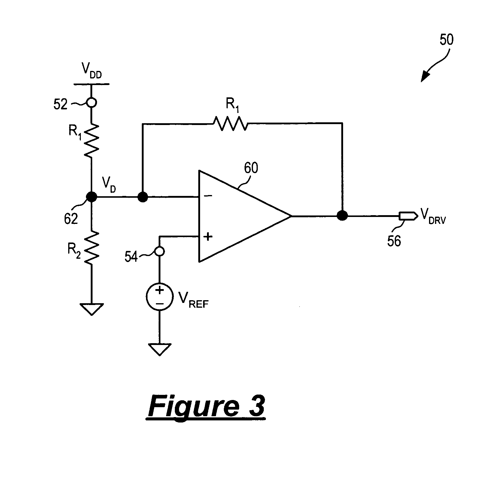
[0017] In accordance with the principles of the present invention, a voltage multiplier circuit incorporates a control circuit for providing dynamic control of the voltage multiplier output voltage. Specifically, the voltage multiplier output voltage is controlled through the dynamic control of a driving voltage coupled to drive the one or more voltage multiplier stages of the voltage multiplier circuit. In one embodiment, the control circuit controls the output voltage of a multi-stage voltage multiplier circuit through the continuous control of the input voltage to the first voltage multiplier stage. In this manner, the output voltage of the first voltage multiplier stage is made independent of the variations of the input power supply voltage VDD and the output voltage of the remaining voltage multiplier stages of the voltage multiplier circuit is the sum of this Vdd-independent voltage and a multiple of the power supply voltage.

[0018] More specifically, the voltage multiplier ci...


PUM


Abstract

A voltage multiplier circuit includes a control circuit and a first voltage multiplier stage. The control circuit receives a power supply voltage and a reference voltage and provides a first output voltage being the difference between a first selected voltage and the power supply voltage where the first selected voltage is a function of the reference voltage and is independent of variations in the power supply voltage. The first voltage multiplier stage receives the first output voltage and a clock voltage signal having a clock voltage value and provides a second output voltage being the sum of the first output voltage and the clock voltage value. When the clock voltage value is equal to the power supply voltage, the second output voltage of the first voltage multiplier stage is the first selected voltage independent of any power supply voltage variations.

Description

FIELD OF THE INVENTION [0001] The invention relates to voltage multiplier circuits and, in particular, to a voltage multiplier circuit incorporating a control circuit for providing dynamic control of the output voltage. DESCRIPTION OF THE RELATED ART [0002] Voltage multiplier circuits for generating operational voltages higher than a power supply voltage provided from an external source are known. Typically, a voltage multiplier circuit receives two fixed input voltages, one of the input voltages being the power supply voltage and the other being a clock voltage. The voltage multiplier provides an output voltage being the sum of its two input voltages. When the two fixed input voltages are the same, the voltage multiplier circuit generates an output voltage that is N times the power supply voltage where N is the number of voltage multiplication stages. In general, a voltage multiplier circuit may include two or more voltage multiplier stages to provide an output voltage that is two ...

Claims


Application Information

Patent Timeline
IPC IPC(8): G05F1/10
CPCH02M3/073
Inventor SMITH, PAULSHAW, JOHN
Owner MICREL
Features
  • R&D
  • Intellectual Property
  • Life Sciences
  • Materials
  • Tech Scout
  • Unparalleled Data Quality
  • Higher Quality Content
  • 60% Fewer Hallucinations
Learn More