
High voltage tank assembly for radiation generator

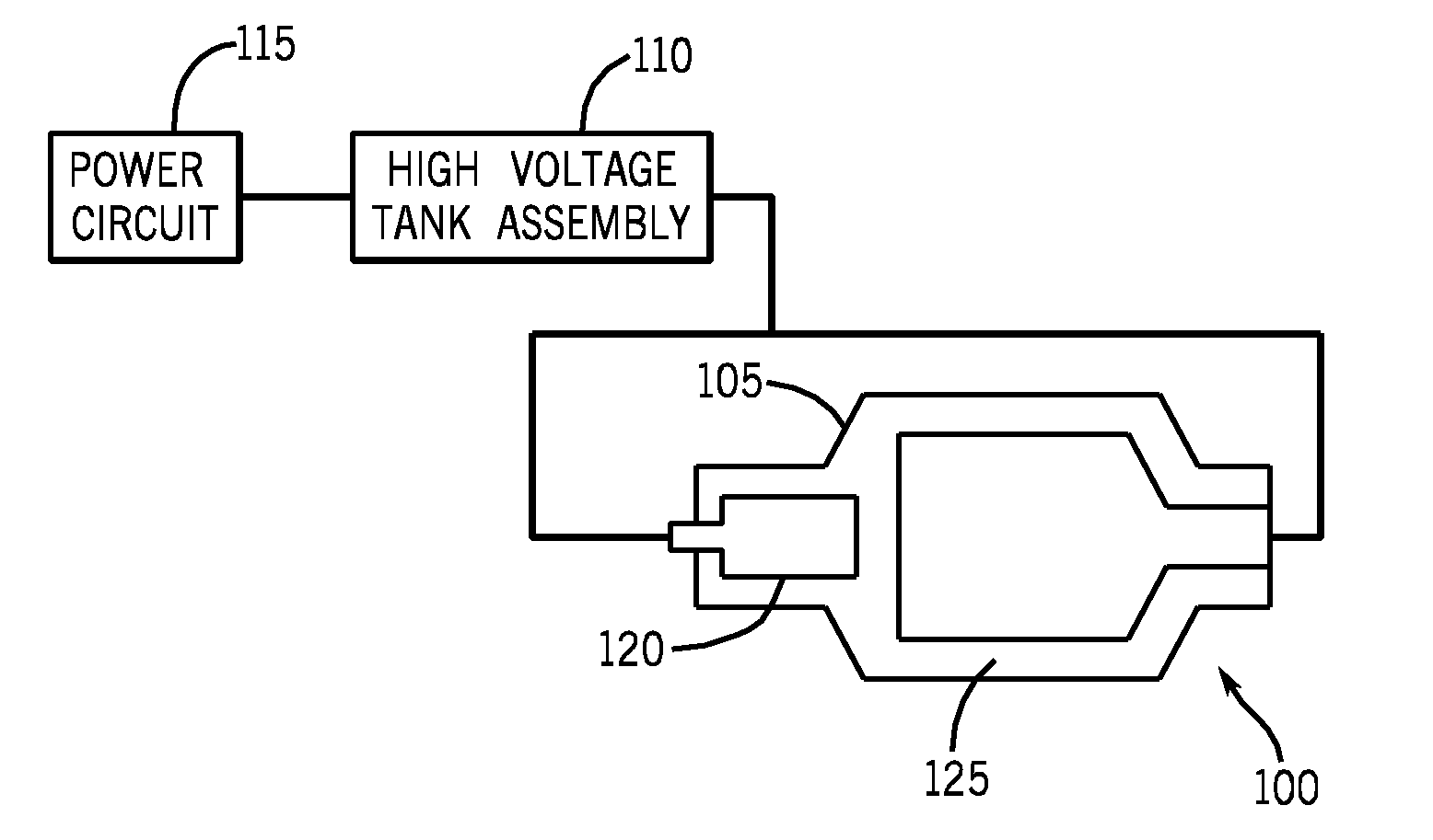
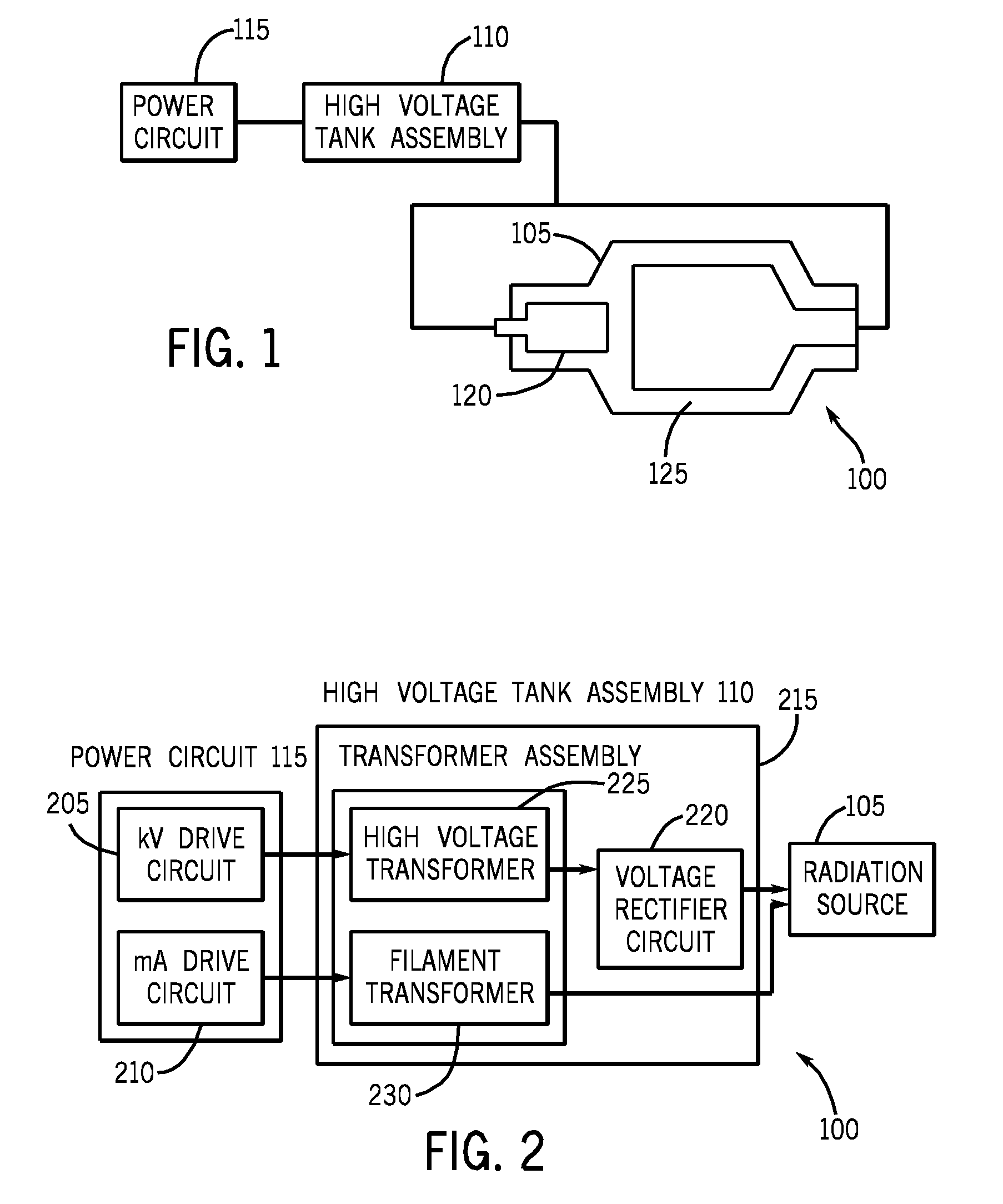
a high-voltage tank and radiation generator technology, applied in the direction of printed resistor incorporation, printed capacitor incorporation, printed circuit aspects, etc., can solve the problems of filament transformer bulkiness, ceramic insulation capacitors generally not suited for such an application, and the dimension of printed circuit boards

Inactive Publication Date: 2009-02-12
GENERAL ELECTRIC CO
View PDF15 Cites 24 Cited by
  • Summary
  • Abstract
  • Description
  • Claims
  • Application Information

AI Technical Summary

Problems solved by technology

The voltage rectifier circuit and the transformer assembly are among bulky modules of the radiation generator.
Thus, the filament transformer may include one or more insulation sheets to strengthen the insulation between the secondary winding and the core thereby resulting in bulkiness of the filament transformer.
One limitation associated with use of the diode series is with regard to the dimension of the printed circuit board required to host the diode series.
Capacitors with ceramic insulation are generally not suited for such an application as the peak power requirement is high and the duration is long.
The ceramic capacitors carry a risk of loss of performance (high ripple) due to losses in ceramic.
Alternatives such as high voltage capacitors with mica or polypropylene insulation generally result in bulky design for the radiation generator.
Thus, most of the activity with regard to the built in capacitance in the printed circuit board is concentrated around treatment of such capacitance for the purpose of decoupling, thereby inefficiently using the in built capacitance in the printed circuit board.

Method used


Image

  • High voltage tank assembly for radiation generator
  • High voltage tank assembly for radiation generator
  • High voltage tank assembly for radiation generator

Examples


Embodiment Construction

[0029]In the following detailed description, reference is made to the accompanying drawings that form a part hereof, and in which is shown by way of illustration specific embodiments, which may be practiced. These embodiments are described in sufficient detail to enable those skilled in the art to practice the embodiments, and it is to be understood that other embodiments may be utilized and that logical, mechanical, electrical and other changes may be made without departing from the scope of the embodiments. The following detailed description is, therefore, not to be taken in a limiting sense.

[0030]The invention may take form in various components and arrangements of components. The drawings are only for purposes of illustrating various embodiments and are not to be construed as limiting the invention.

[0031]An imaging apparatus such as a computed tomography apparatus and an X ray apparatus, configured to image objects, comprises a radiation generator, a radiation detector and a dat...


PUM


Abstract

In one embodiment, a voltage rectifier circuit for a radiation generator is provided. The voltage rectifier circuit is configured to be used in a voltage multiplier circuit and a voltage doubler circuit. The voltage rectifier circuit comprises at least one first printed circuit board and at least one second printed circuit board coupled to each other using a plurality of connectors. Further, each printed circuit board comprises, a first terminal, a second terminal, a third terminal, a diode assembly externally connected between the first terminal and the second terminal and a capacitor assembly embedded between the second terminal and the third terminal.

Description

BACKGROUND OF THE INVENTION[0001]The subject matter described herein generally relates to a radiation generator and more particularly to a high voltage tank assembly used in a radiation generator.[0002]An imaging device comprising a ‘C’ arm incorporates a radiation generator and a radiation detector. The radiation generator generally comprises a radiation source, a high voltage tank assembly configured to energize the radiation source and a power circuit. As the high voltage tank assembly responsible for generating the high voltage required for the operation of the radiation source represents a substantial part of the overall size of the radiation generator, it is desirable to provide a compact high voltage tank assembly.[0003]Further, the high voltage tank assembly comprises a voltage rectifier circuit and a transformer assembly coupled to the voltage rectifier circuit. The voltage rectifier circuit and the transformer assembly are among bulky modules of the radiation generator.[00...

Claims


Application Information

Patent Timeline
Patent Type & Authority Applications(United States)
IPC IPC(8): H05G1/24H05G1/12
CPCH05G1/04H05K1/0254H05K1/144H05K2201/10174H05K1/167H05K2201/09309H05K2201/09718H05K1/162
Inventor SUNDARAM, SENTHIL KUMARKRISHNAMOORTHY, ROHINI
Owner GENERAL ELECTRIC CO
Learn More