Solar cell adjustment system, related method, and minimum current detection and control system

a solar cell and adjustment system technology, applied in photovoltaic monitoring, ac network circuit arrangement, instruments, etc., can solve the problems of inverse bias, shaded solar cell modules, and shaded modules, and achieve simplified circuit configuration, reduce ripple current, and reduce the operating voltage of shaded modules

Active Publication Date: 2016-10-06
JAPAN AEROSPACE EXPLORATION AGENCY
View PDF0 Cites 28 Cited by
  • Summary
  • Abstract
  • Description
  • Claims
  • Application Information

AI Technical Summary

Benefits of technology

[0109]The solar cell adjustment system according to each of the first to third aspects of the present invention makes it possible to, during occurrence of partial shading, relatively lower an operating voltage of a shaded module, as compared to that of a insolated module, and therefore adequately set an equivalent output resistance Rout, considering electrical characteristics of a solar cell during occurrence of partial shading to allow both the insolated module and the shaded module to operate around the MPP even during occurrence of partial shading.
[0110]That is, the solar cell adjustment system according to the present invention functions as a partial shading compensation device.
[0111]Further, the equivalent output resistance Rout may be adjusted by controlling a frequency of the partial shading compensation device depending on an occurrence state of partial shading. In this case, it is also possible to achieve the same object (to allow each module to operate around the M...

Problems solved by technology

In the case where a plurality of solar cell modules are used in the form of a string constructed by connecting them in series, the solar cell modules can be partially shaded (shadowed) (this shading (shadowing) will hereinafter be referred to as “partial shading”), and this causes a variation in characteristics of the solar cell modules, thereby leading to a risk that the...

Method used


Image

  • Solar cell adjustment system, related method, and minimum current detection and control system
  • Solar cell adjustment system, related method, and minimum current detection and control system
  • Solar cell adjustment system, related method, and minimum current detection and control system

Examples


first embodiment

Configuration of Solar Cell Adjustment System

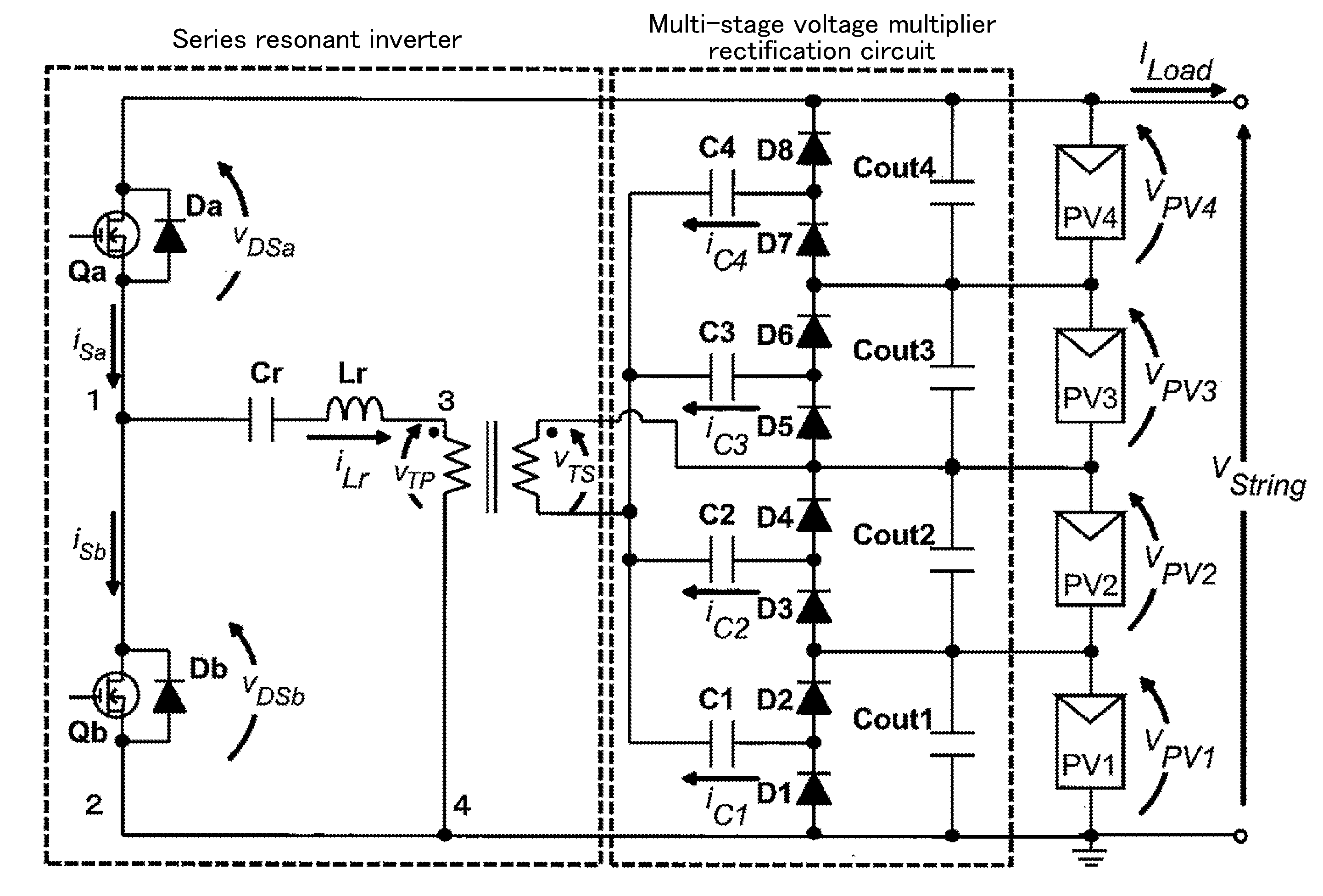
[0234]FIG. 8 depicts a solar cell adjustment system for four series-connected solar cell modules PV1 to PV4, according to a first embodiment of the present invention. A circuit configuration depicted in FIG. 8 is one example in which the PV pseudo-equalizer in FIGS. 6 and 7 is composed of a series resonant inverter and a multi-stage voltage multiplier rectification circuit.

Series Resonant Inverter

[0235]The series resonant inverter is constructed by: parallel-connecting two flywheel diodes Da and Db, respectively, to two series-connected switches Qa and Qb to form a half-bridge cell; serial-connecting a capacitor Cr and an inductor Lr to the half-bridge cell; and providing a transformer between them and the multi-stage voltage multiplier rectification circuit.

[0236]In FIG. 8, iSa and iSb denote, respectively, two currents each flowing through a respective one of the switches Qa and Qb, and VDSa and VDSb denote, respectively, two voltages e...

second embodiment

[0430]FIG. 26 depicts a solar cell adjustment system according to a second embodiment of the present invention.

[0431]In the second embodiment, a second voltage multiplier circuit is employed in combination with the first embodiment depicted in FIG. 8 to form a symmetrical circuit configuration, thereby making it possible to reduce a ripple current flowing through each module.

[0432]Assume a situation where a solar cell module PV1 is shaded in the solar cell adjustment system according to the second embodiment depicted in FIG. 26. FIGS. 27a to 27d depict pathways of currents flowing through a circuit in modes 2 to 4 and 1, when ON / OFF states of switches Qa and Qb are switched according to the graph of VGS in FIG. 9, in the above situation.

[0433]It should be noted that, in these figures, capacitor Cout1a to Cout4a and Cout1b to Cout4b are omitted.

[0434]In the modes 2 and 3, a discharge current of an intermediate capacitor C1b routed through a secondary winding of a transformer flows as...

third embodiment

[0488]For example, the solar cell adjustment system according to the fourth aspect of the present invention can be obtained by multistage-connecting one buck-boost converter of a SEPIC converter, a Zeta converter and a Cuk converter depicted in FIGS. 40a to 40c, to a string, as mentioned later.

[0489]The Cuk converter is a “polarity-reversing converter” in which polarities of input and output signals are reversed. Thus, in the case where it is applied to the solar cell adjustment system according to the fourth aspect of the present invention, the system needs to be based on a configuration using a transformer as depicted in FIG. 40c.

Configuration of Solar Cell Adjustment System

[0490]FIGS. 41 to 43 depict solar cell adjustment systems each obtained by multistage-connecting a respective one of the SEPIC converter, the Zeta converter and the Cuk converter depicted in FIGS. 40a to 40c, to four series-connected solar cell modules PV1 to PV4, according to first to third embodiments of the...


PUM


Abstract

[Problem] It is intended to provide a system, a related method and a minimum current detection and control system for, even when partial shading occurs in a string composed of a series connection of a plurality of solar cell modules, maintaining an output current of the whole.
[Solution] By inputting an output voltage of the string into an inverter to convert the output voltage into an AC voltage and applying the AC voltage to the string via a multi-stage voltage multiplier rectification circuit, a compensation current is supplied to a shaded module on a priority basis to maintain an output current of the whole string while lowering an operating voltage of the shaded module by impedance generated on a pathway of the compensation current. Further provided are a system and the like constructed by multistage-connecting an output-side circuit section of one of various types of converters to the solar cell modules, and configured to supply a compensation current from the converter section to the shaded module on a priority basis.

Description

TECHNICAL FIELD[0001]The present relates to a partial shading compensation device for, when partial shading occurs in a string composed of a series connection of a plurality of solar cell modules (solar cell module string), equalizing electrical characteristics of the solar cell modules in a pseudo manner.BACKGROUND ART[0002]A solar cell is designed to convert light energy into electric power by means of a photovoltaic effect, and typically has a structure in which a p-type semiconductor and an n-type semiconductor are joined together, and an electrode and others are attached thereto.[0003]An operating characteristic of a solar cell changes in response to changes in insolation condition or temperature, and a relationship between a voltage applied to a solar cell and a current flowing through the solar cell and a relationship between the applied voltage and an electric power generated from the solar cell are generally represented by operating characteristic curves depicted in FIG. 1....

Claims


Application Information

Patent Timeline
IPC IPC(8): H02J3/38H02S40/36H02S40/32
CPCH02J3/383H02S40/36H02S40/32G05F1/67H02S50/10H02J2300/26H02J3/381Y02E10/56
Inventor UNO, MASATOSHIKUKITA, AKIO
Owner JAPAN AEROSPACE EXPLORATION AGENCY
Why Eureka
Try Eureka