High-dynamic range low ripple voltage multiplier

a voltage multiplier and dynamic range technology, applied in the field of integrated circuits, can solve the problems of undesirable voltage ripple, large number of components required, and linear regulators for generating sub-supply voltages that produce undesirable voltage ripples

Active Publication Date: 2009-06-04
NXP USA INC
View PDF5 Cites 25 Cited by
  • Summary
  • Abstract
  • Description
  • Claims
  • Application Information

AI Technical Summary

Problems solved by technology

However, an undesirable large number of components are required as a result of the providing many different internal voltages with the corresponding regulators and pumps.
In addition, impedance degradation is a problem that occurs with charge pumps operated over a large output voltage range.
Furthermore, undesirable voltage ripple is produced via linear regulators for generating sub-supply voltages.

Method used


Image

  • High-dynamic range low ripple voltage multiplier
  • High-dynamic range low ripple voltage multiplier
  • High-dynamic range low ripple voltage multiplier

Examples


Embodiment Construction

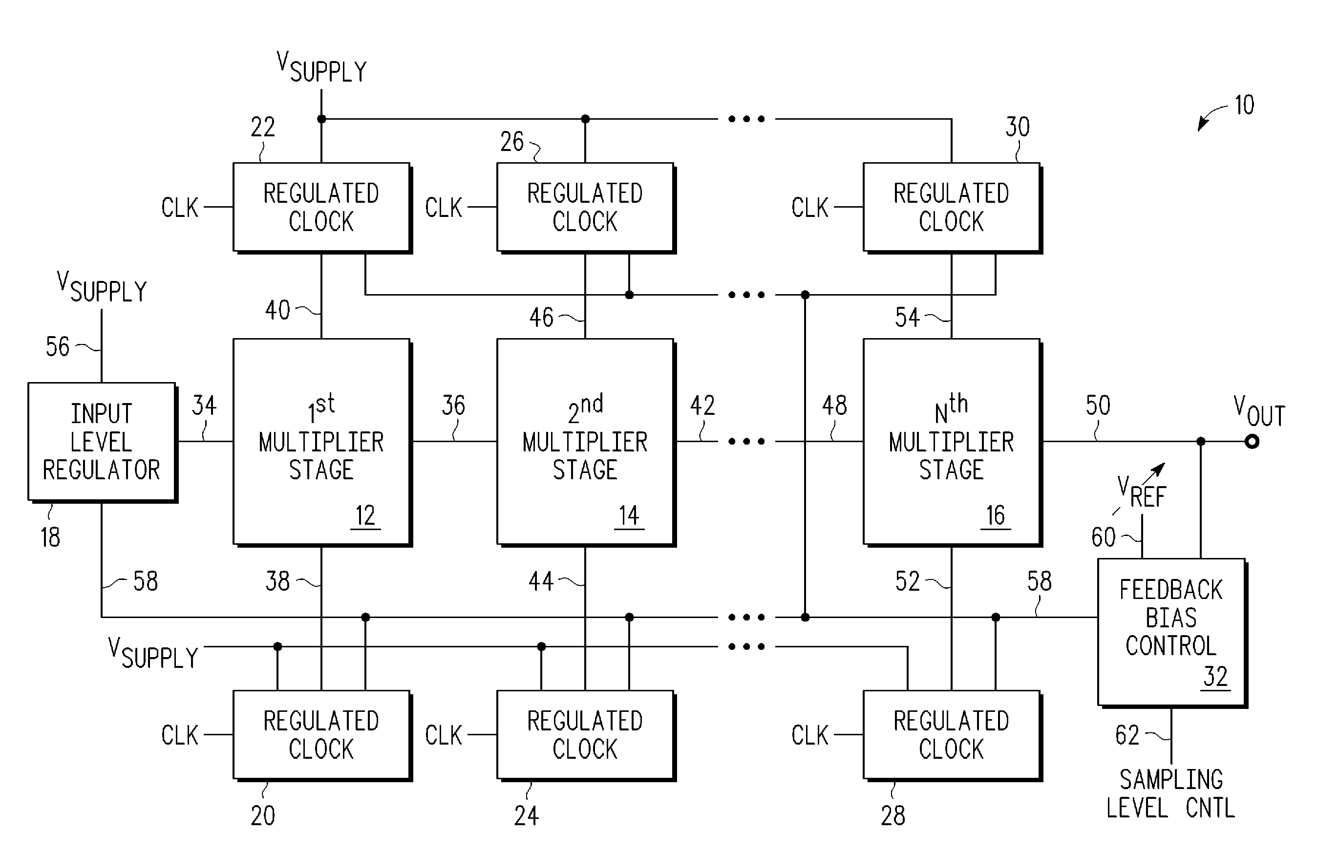
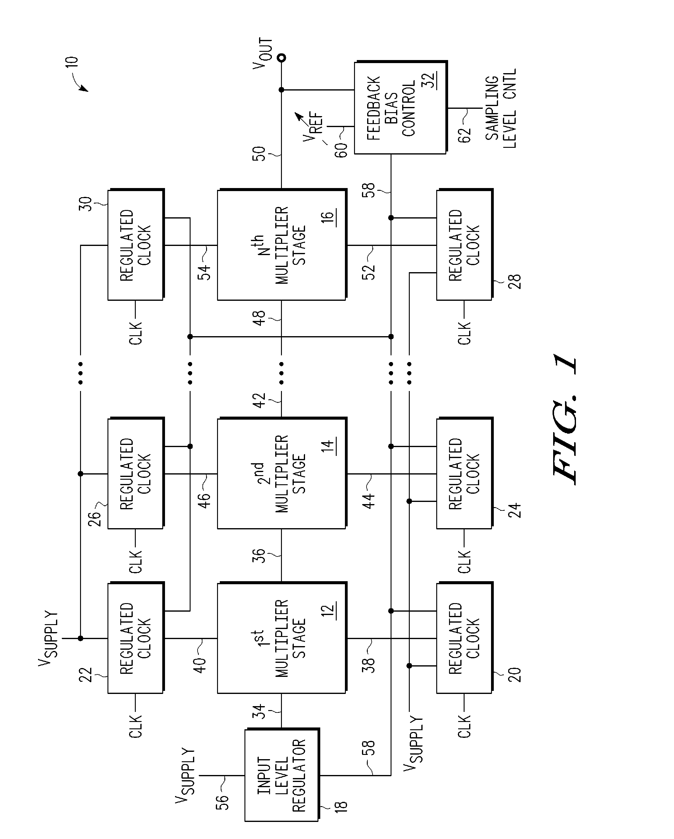
[0011]The voltage multiplier according to the embodiments of the present disclosure is advantageously suited to meet a number of voltage generation needs within an integrated circuit. While most multiplier circuits generate a multiplier factor of greater than one (i.e., >1), the voltage multiplier according to the embodiments of the present disclosure advantageously enables generation by the same voltage multiplier of (i) a multiplier of less than one (i.e., 1). In one embodiment, the voltage multiplier is capable of a multiplier range from less than one to more than one by a multiplier factor of three (3×). As a result, one voltage generator supplies many different voltages and loads for a given integrated circuit, for example, one or more types of FLASH memory devices.

[0012]In addition, the voltage multiplier circuit according to the embodiments of the present disclosure enables generation of a wide range of voltages with relatively small ripple. Previous known circuits for genera...


PUM


Abstract

A voltage multiplier (10) including a first clocked multiplier stage (12) having an input and an output and a second clocked multiplier stage (14, 16) having an input and an output is provided. The voltage multiplier further includes an input level regulator (18) coupled to the input of the first multiplier stage. The voltage multiplier further includes a feedback bias control circuit (32) coupled to the input level regulator, wherein the feedback bias control circuit is further coupled to receive the output (50) of the second multiplier stage, and wherein the feedback bias control circuit generates a feedback signal (58) affecting an output of the input level regulator based on a comparison between a voltage proportional to a voltage at the output of the second clocked multiplier stage and a reference voltage.

Description

BACKGROUND[0001]1. Field[0002]This disclosure relates generally to integrated circuits, and more specifically, to high dynamic range low ripple voltage multipliers.[0003]2. Related Art[0004]Flash memory devices require many different internal voltages to be generated within the memory device. Some voltages comprise voltages less than the supply voltage, also referred to as sub-supply voltages, and are generated, for example, by linear regulators. Other voltages are greater than the supply voltage and are generated by charge pumps (also referred to as voltage multipliers). However, an undesirable large number of components are required as a result of the providing many different internal voltages with the corresponding regulators and pumps. In addition, impedance degradation is a problem that occurs with charge pumps operated over a large output voltage range. Furthermore, undesirable voltage ripple is produced via linear regulators for generating sub-supply voltages.[0005]Accordingl...

Claims


Application Information

Patent Timeline
Patent Type & Authority Applications(United States)
IPC IPC(8): G05F1/10
CPCH02M3/073
Inventor CHOY, JON S.
Owner NXP USA INC
Why Eureka
Try Eureka