
Input device including a scroll wheel assembly

Inactive Publication Date: 2006-12-28
MICROSOFT TECH LICENSING LLC
View PDF2 Cites 28 Cited by
  • Summary
  • Abstract
  • Description
  • Claims
  • Application Information

AI Technical Summary

Benefits of technology

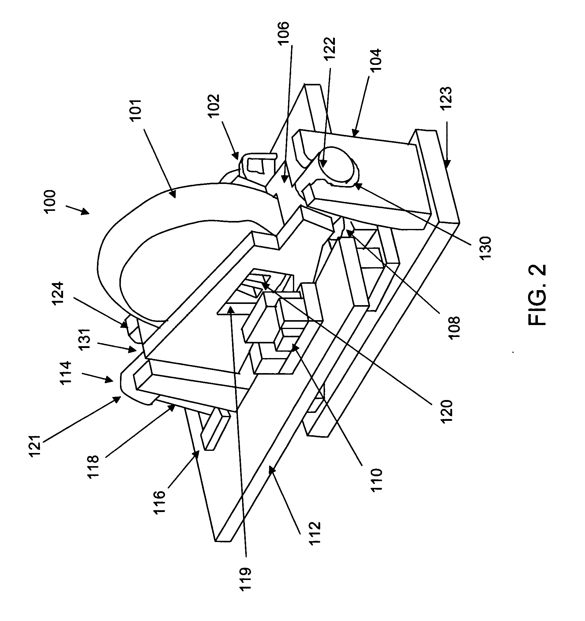
[0010] In another aspect, the finger-engagable member may be associated with an axle extending from the finger-engagable member along a tilt axis. The axle may contact or be contained within a holder such as a tower or Z-carrier. The holder may be fitted for the axle such that the corresponding shape of an opening in the holder for holding the axle and the shape of the cross section of the axle prevent excessive pivoting of the finger-engagable member.

Problems solved by technology

When the user needs to move the image horizontally across the display screen, the user must typically stop what he or she is doing and perform a number of tedious and potentially frustrating steps.
Locating the scroll bar can be very difficult for people with bad eyesight, small display screens and / or poor hand-eye coordination.
As a result, the user will waste time and delay the completion of his project while fumbling to find the bottom horizontal scroll bar.
These delays can cause the user great frustration and unnecessary stress that is magnified when he or she is operating under a deadline.
Instead, the image will move vertically relative to the display screen and erroneously change the displayed image.
This error will force the user to take additional steps to reposition the desired image on the display screen.
Unfortunately, repositioning an image can lead to errors if the image is being amended.
As a result, he may amend the wrong section of the image.
However, this arrangement has drawbacks as the two wheels take up valuable upper surface area on the mouse which could be used for supporting the hand of the user or for additional input keys.
The smaller sized scroll wheels make the scrolling more difficult to control.
Additionally, the location of the horizontal scroll wheel is inconvenient for effective control.

Method used


Image

  • Input device including a scroll wheel assembly
  • Input device including a scroll wheel assembly
  • Input device including a scroll wheel assembly

Examples


Embodiment Construction

[0022] In the following description of the various embodiments, reference is made to the accompanying drawings, which form a part hereof, and in which is shown by way of illustration various embodiments in which the invention may be practiced. It is to be understood that other embodiments may be utilized and structural and functional modifications may be made without departing from the scope of the present invention.

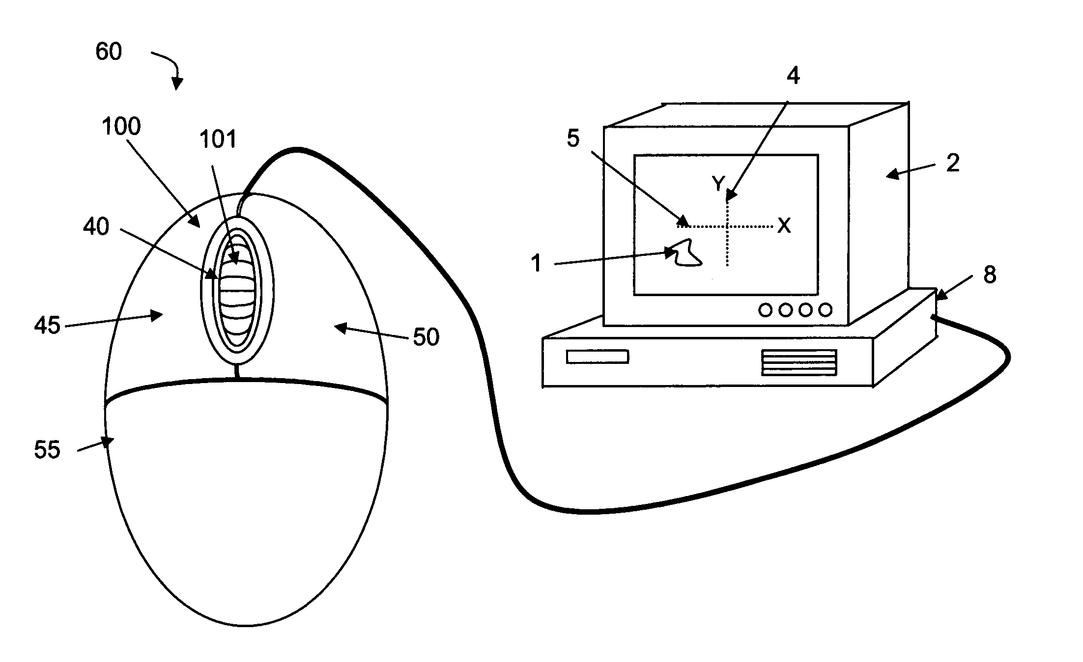
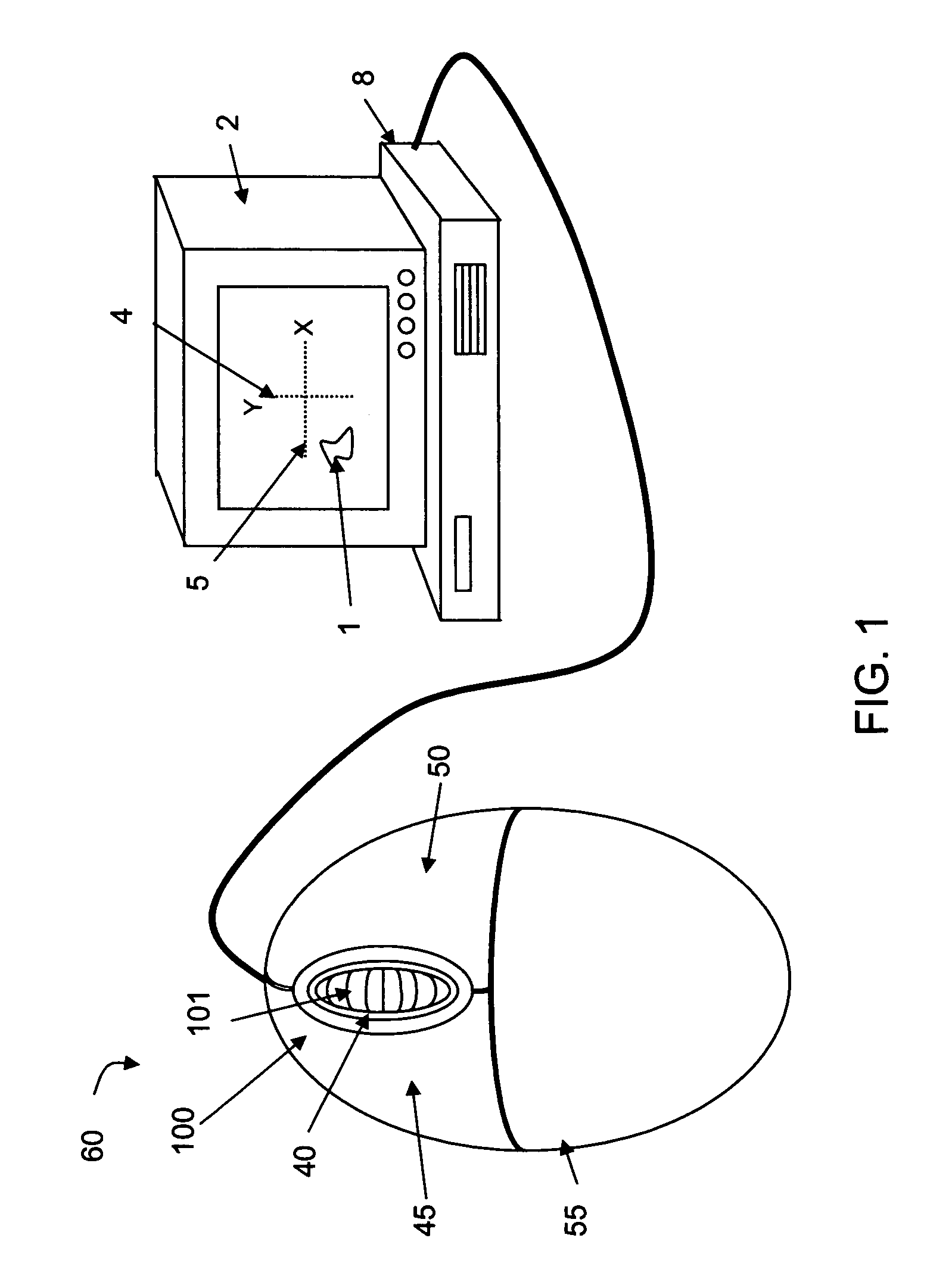
[0023]FIG. 1 illustrates an example of a computer input device including a scroll wheel assembly 100 having a finger-engagable control member 101 (e.g., scroll wheel) that can be used with different types of computer input devices for scrolling an image in multiple directions and along multiple axes (X, Y) relative to a display screen 2 used with a host computer 8, another type of computing device, or an internet appliance. As shown in FIG. 1, one embodiment of the scroll wheel assembly 100 according to the present invention can be located within a mouse 60. Alternative...


PUM


Abstract

An input device including a scroll wheel assembly for moving an image in multiple directions on a display screen. The scroll wheel assembly may include a finger-engagable control member that may be endlessly rotated about a rotation axis and a tilt sensor containing a tilt contact member coplanar with the finger-engagable control member and oriented in a substantially vertical, downward orientation such that pivoting of the finger-engagable control member may move the tilt contact member laterally to contact laterally disposed contact switches. In another example, the finger-engagable control member contains a flexible blade at an underside for biasing the scroll wheel assembly to an upright position.

Description

BACKGROUND [0001] Scroll wheels have been provided on computer mice and used by computer operators to move an image relative to a display screen of a host computer. A scroll wheel assembly includes a rotatable scroll wheel and a sensor that are typically included in a housing for a peripheral computer device such as a mouse. Typically, a portion of the scroll wheel protrudes upwardly out of an opening in its housing and is rotated in order to vertically scroll the image along the screen. [0002] Scrolling, as used herein, describes the movement of an image relative to a display screen in a particular direction as such term is commonly used in the art. For example, the term “scroll down” as used herein relates to moving the viewable contents of a file (such as a text document or image) relative to display screen by an amount to produce an effect of moving down in the document or image. Similarly, the terms scroll up, scroll left and scroll right relate to moving the viewable contents ...

Claims


Application Information

Patent Timeline
IPC IPC(8): G09G5/08
CPCG06F3/0362G06F3/0338G06F3/0354
Inventor BOHN, DAVID D.KOO, JAMES YUAN-CHAOPEDERSEN, MATTHEWWAHL, ERIC
Owner MICROSOFT TECH LICENSING LLC
Learn More