X-ray CT apparatus

a computed tomography and x-ray technology, applied in tomography, instruments, applications, etc., can solve the problems of inability to cope with the fluctuation of the cycle of biomedical signals, deterioration of image quality, etc., and achieve high temporal resolution, improved image quality, and high temporal resolution

Inactive Publication Date: 2006-12-28
GE MEDICAL SYST GLOBAL TECH CO LLC
View PDF16 Cites 19 Cited by
  • Summary
  • Abstract
  • Description
  • Claims
  • Application Information

AI Technical Summary

Benefits of technology

[0049] According to an X-ray CT apparatus or an X-ray CT image reconstruction method in which the present invention is implemented, when an X-ray CT apparatus including a two-dimensional area X-ray detector that has a matrix structure and is represented by a multi-array X-ray detector or a flat-panel X-ray detector performs a conventional (axial) scan or a cine scan, tomographic images that enjoy improved image quality, that is, a high temporal resolution, and that show states of a subject synchronized with an external sync signal or a biomedical signal are three-dimensionally displayed. Otherwise, a three-dimensional tomographic image that enjoys a high temporal resolution and shows states of a subject synchronized with a plurality of phases of the external sync signal or biomedical signal is displayed. Otherwise, a four-dimensional tomographic image that enjoys a high temporal resolution and shows states of a subject synchronized with the external sync signal or biomedical signal is displayed.

Problems solved by technology

A fluctuation in the cycle of the biomedical signal leads to deterioration of image quality, and therefore poses a problem.
If the moving speed at which a subject is moved in the z direction remains constant, the fluctuation in the cycle of the biomedical signal cannot be coped with, and therefore poses a problem.

Method used


Image

  • X-ray CT apparatus
  • X-ray CT apparatus
  • X-ray CT apparatus

Examples


Embodiment Construction

[0076] The present invention will be described below by taking an illustrated embodiment for instance. Noted is that the present invention will not be limited to the embodiment.

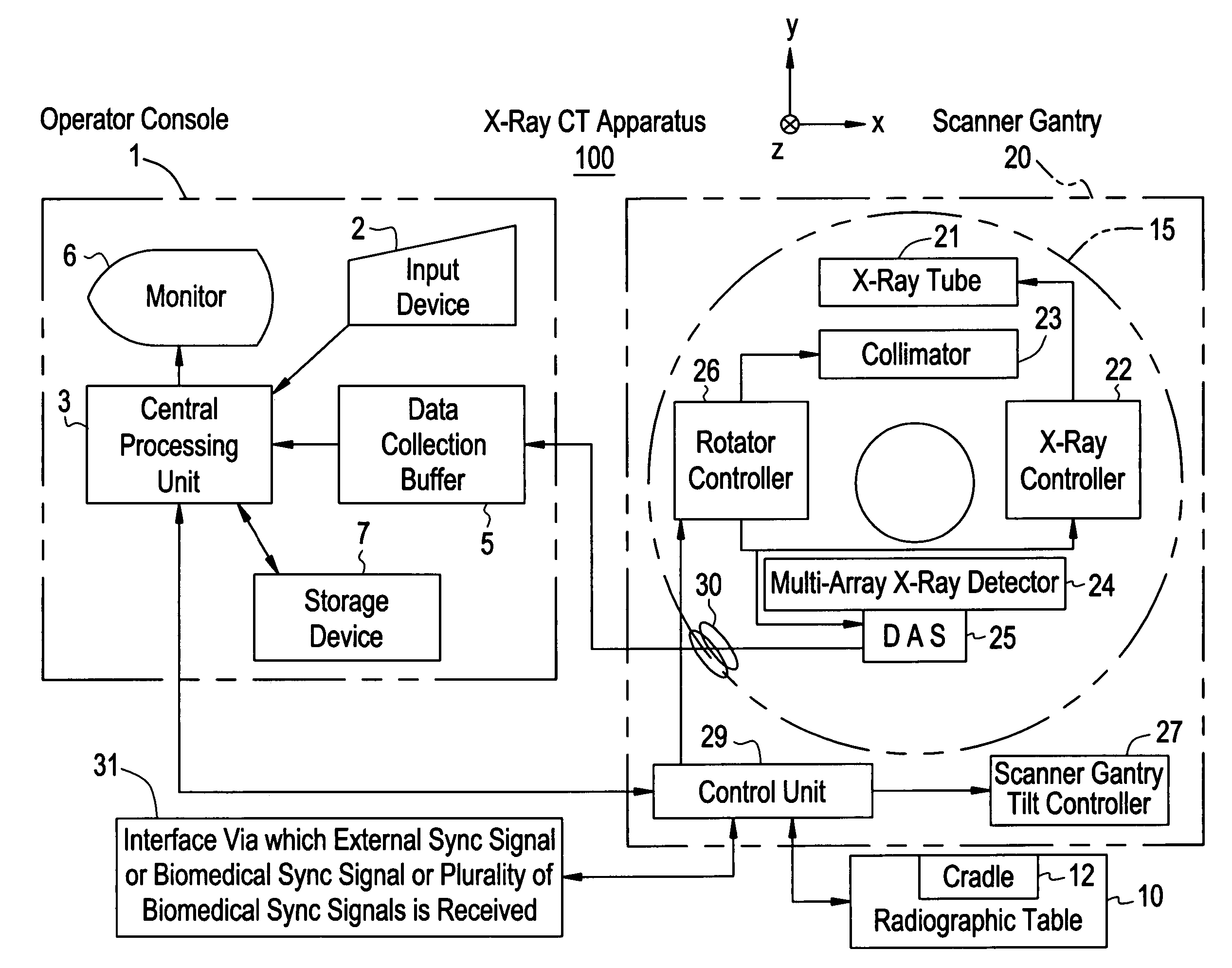
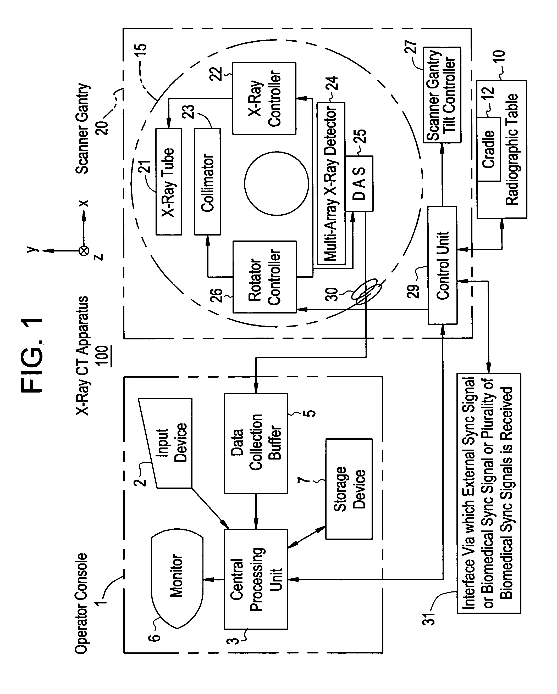
[0077]FIG. 1 is a block diagram showing the configuration of an X-ray CT apparatus in accordance with an embodiment of the present invention. The X-ray CT apparatus 100 includes an operator console 1, a radiographic table 10, and a scanner gantry 20.

[0078] The operator console 1 includes an input device 2 that receives an operator's input, a central processing unit 3 that executes preprocessing, image reconstruction, and post-processing, a data collection buffer 5 that collects X-ray detection data items acquired by the scanner gantry 20, a monitor 6 on which a tomographic image reconstructed based on projection data items produced by preprocessing the X-ray detector data items is displayed, and a storage device 7 in which programs, X-ray detector data items, projection data items, and X-ray tomographic ima...


PUM

PropertyMeasurementUnit
angleaaaaaaaaaa
angleaaaaaaaaaa
view angleaaaaaaaaaa

Abstract

When an X-ray CT apparatus including a two-dimensional X-ray area detector performs a conventional (axial) scan or a cine scan, a plurality of segments of projection data items detected synchronously with an external signal or a biomedical signal is sampled from projection data items acquired during one scan or a plurality of scans. Projection data items corresponding to those detected during a half scan of rotating an X-ray tube by an angle of 180° plus the angle of a fan beam falling on the detector or during a 360° full scan are used to reconstruct a three-dimensional image. Thus, a three-dimensional tomographic image enjoying a high temporal resolution is displayed. Moreover, successive three-dimensional display images showing states of a subject synchronized with respective phases of the external signal or biomedical signal may be displayed as a four-dimensional image.

Description

CROSS REFERENCE TO RELATED APPLICATIONS [0001] This application claims the benefit of Japanese Application No. 2005-184722 filed Jun. 24, 2005. BACKGROUND OF THE INVENTION [0002] The present invention relates to an X-ray computed tomography (CT) method to be implemented in X-ray CT apparatuses for medical or industrial use, and an X-ray CT apparatus to be adapted to the X-ray CT apparatuses for medical or industrial use. More particularly, the present invention relates to conventional (axial) or cine scan synchronous imaging, three-dimensional display, and four-dimensional display or to improvement of image quality. [0003] Conventionally, in X-ray CT apparatuses including a two-dimensional X-ray area detector that has a matrix structure and is represented by a multi-array X-ray detector or a flat-panel X-ray detector, a subject is helically scanned as shown in FIG. 12. One segment that is composed of projection data items acquired during a helical scan, that is synchronous with a ce...

Claims


Application Information

Patent Timeline
Patent Type & Authority Applications(United States)
IPC IPC(8): A61B6/00G01N23/00G21K1/12H05G1/60
CPCA61B6/032A61B6/4085A61B6/027G06T11/005A61B6/541A61B6/03
Inventor NISHIDE, AKIHIKOIMAI, YASUHIROHAGIWARA, AKIRA
Owner GE MEDICAL SYST GLOBAL TECH CO LLC
Why Eureka
Try Eureka