Apparatus and method for obtaining images using a prism

Active Publication Date: 2006-12-28
HID GLOBAL CORP
View PDF21 Cites 29 Cited by
  • Summary
  • Abstract
  • Description
  • Claims
  • Application Information

AI Technical Summary

Benefits of technology

[0012] An improved apparatus and method for obtaining images through a prism is provided. In an embodiment, a thin fingerprint prism wedge, with a geometry designed to minimize foreshortening and maximize contrast is

Problems solved by technology

If someone else tries to log in as the same person, their biometric information does not fully match, so the system will not allow them to log in.
However, the inventor has foun

Method used


Image

  • Apparatus and method for obtaining images using a prism
  • Apparatus and method for obtaining images using a prism
  • Apparatus and method for obtaining images using a prism

Examples


example fingerprint

Scanning Systems

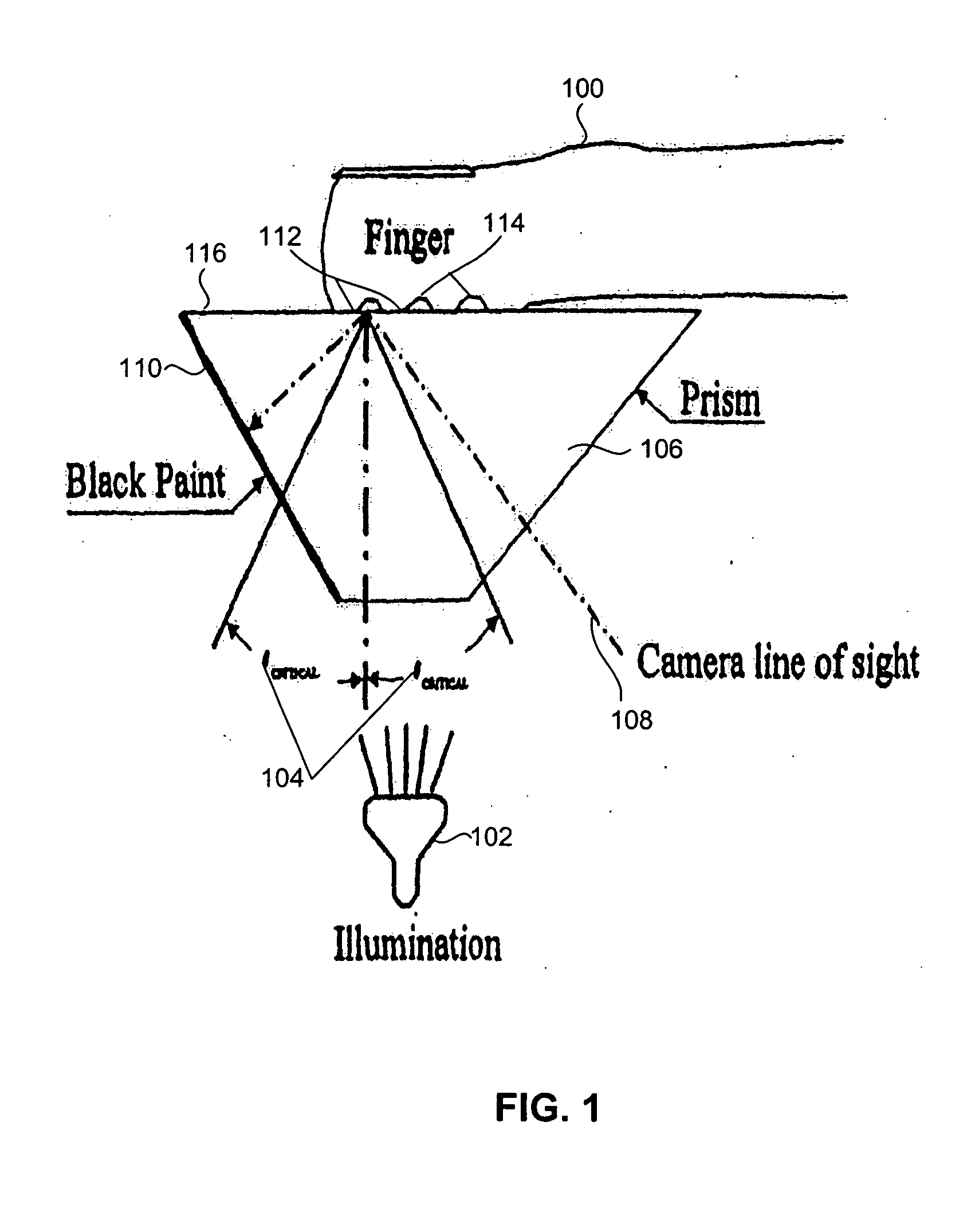
[0046]FIG. 1 is a partial side sectional view of a fingerprint scanner. It has a prism 106, illumination source 102 and optional black paint on non-platen surface 110 of prism 106 and a platen surface 116 against which finger 100 is placed. Illumination source 102 emits light within critical angle 104 that passes through prism 106, is reflected by the internal surface of platen side 116 of prism 106 and is imaged by an image sensor or camera positioned along the camera line of sight, optical path 108. Platen surface 116 can be a surface of prism 300 as shown or alternatively platen surface 116 can be a surface of a thin transparent material, such as a sheet of silicone rubber, placed on the prism. To achieve total internal reflection (TIR), optical path 108 is positioned outside the critical angle 104. In some cases an optical sub-system might be employed to create optical path 108 between the internal surface of platen 116 and the camera if the camera cannot be posi...

example embodiments

[0052] The inventor has determined that foreshortening of an image can be overcome by using internal surface reflection instead of total internal reflection (TIR) by designing a thin wedge prism that allows the optical path to be perpendicular to a platen surface and at the same time maintain sufficient contrast.

[0053] In an embodiment, the apparatus takes advantage of the internal reflection properties of a prism at angles less than the critical angle for TIR. By changing the position of the light source, different aspects of the platen surface 116 can be viewed while minimizing foreshortening.

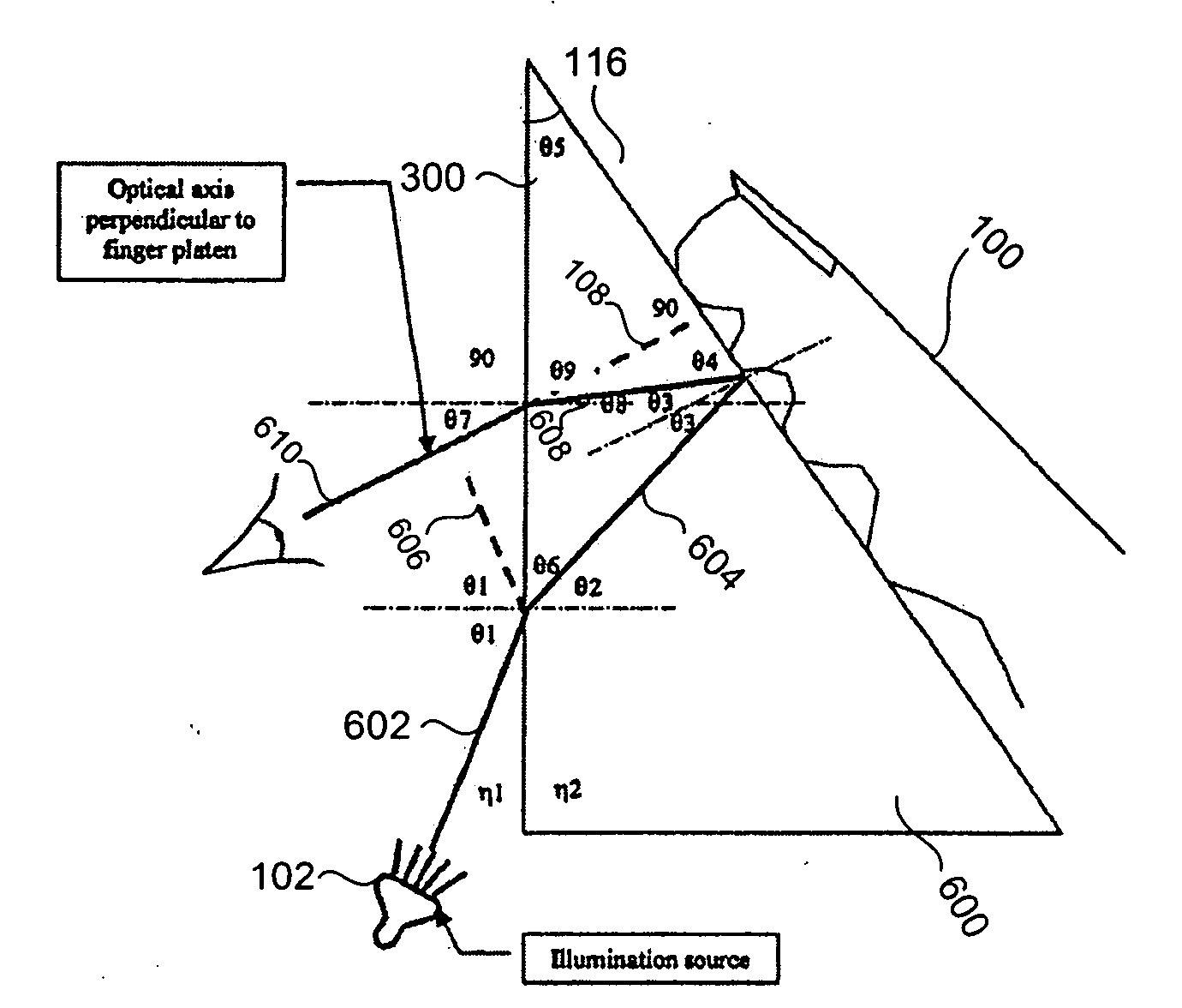
[0054]FIG. 6 illustrates a preferred embodiment employing a thin wedge prism that allows an optical path 108 to be perpendicular to platen surface 116 thereby minimizing the effects of foreshortening. The smaller prism angle 300 of thin wedge prism 600 also minimizes image foreshortening. The prism 600 is designed to operate inside the critical angle 104 and still have sufficient contrast b...


PUM


Abstract

An improved apparatus and method for obtaining images through a prism are provided. In an embodiment, a thin fingerprint prism wedge, with a geometry designed to minimize foreshortening and maximize contrast, is provided in an optical path between an optical sensor and an object to be imaged. In some embodiments, the apparatus operates on the principle of internal surface reflections instead of total internal reflection (TIR).

Description

CROSS-REFERENCE TO RELATED APPLICATIONS [0001] This application claims the benefit of U.S. Provisional Application Ser. No. 60 / 689,350, filed Jun. 10, 2005, incorporated herein by reference in its entirety.FIELD OF THE INVENTION [0002] The present invention relates generally to the field of obtaining images through an optical path including a prism or an element providing a similar function. BACKGROUND [0003] Biometrics is the science and technology of authentication (i.e. establishing the identity of an individual) by measuring the person's physiological or behavioral features. The term is derived from the Greek words “bios” for life and “metron” for degree. [0004] In information technology, biometrics usually refers to technologies for measuring and analyzing human physiological characteristics such as fingerprints, eye retinas and irises, voice patterns, facial patterns, and hand measurements; especially for authentication purposes. [0005] In a typical biometric system, a person ...

Claims


Application Information

Patent Timeline
IPC IPC(8): G06K9/00
CPCG06K9/00046G06V40/1324
Inventor MCCLURG, GEORGE W.
Owner HID GLOBAL CORP
Why Eureka
Try Eureka