Spectroscopic analysis of a biological fluid reacted with an enzyme
a biological fluid and enzyme technology, applied in biochemical apparatus and processes, specific use bioreactors/fermenters, biomass after-treatment, etc., can solve the problems of patient death, high glucose levels, and hinder the recovery of patients
- Summary
- Abstract
- Description
- Claims
- Application Information
AI Technical Summary
Problems solved by technology
Method used
Image

Examples
third embodiment
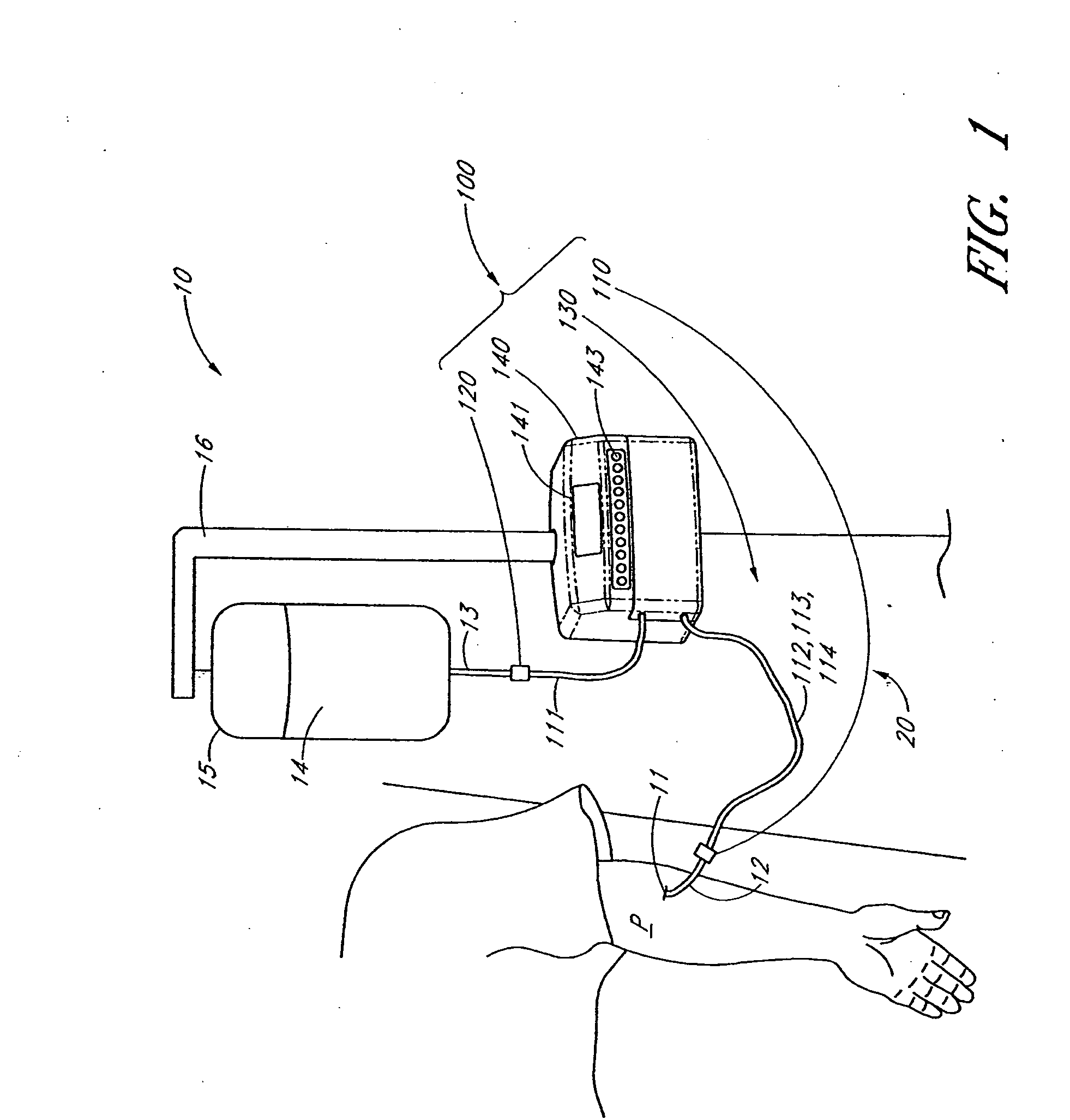
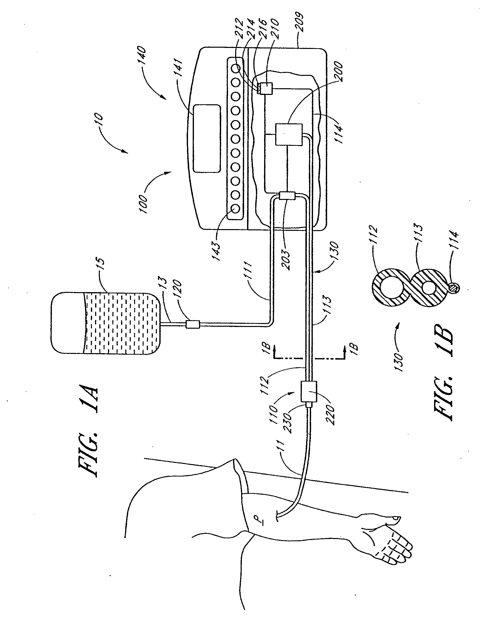
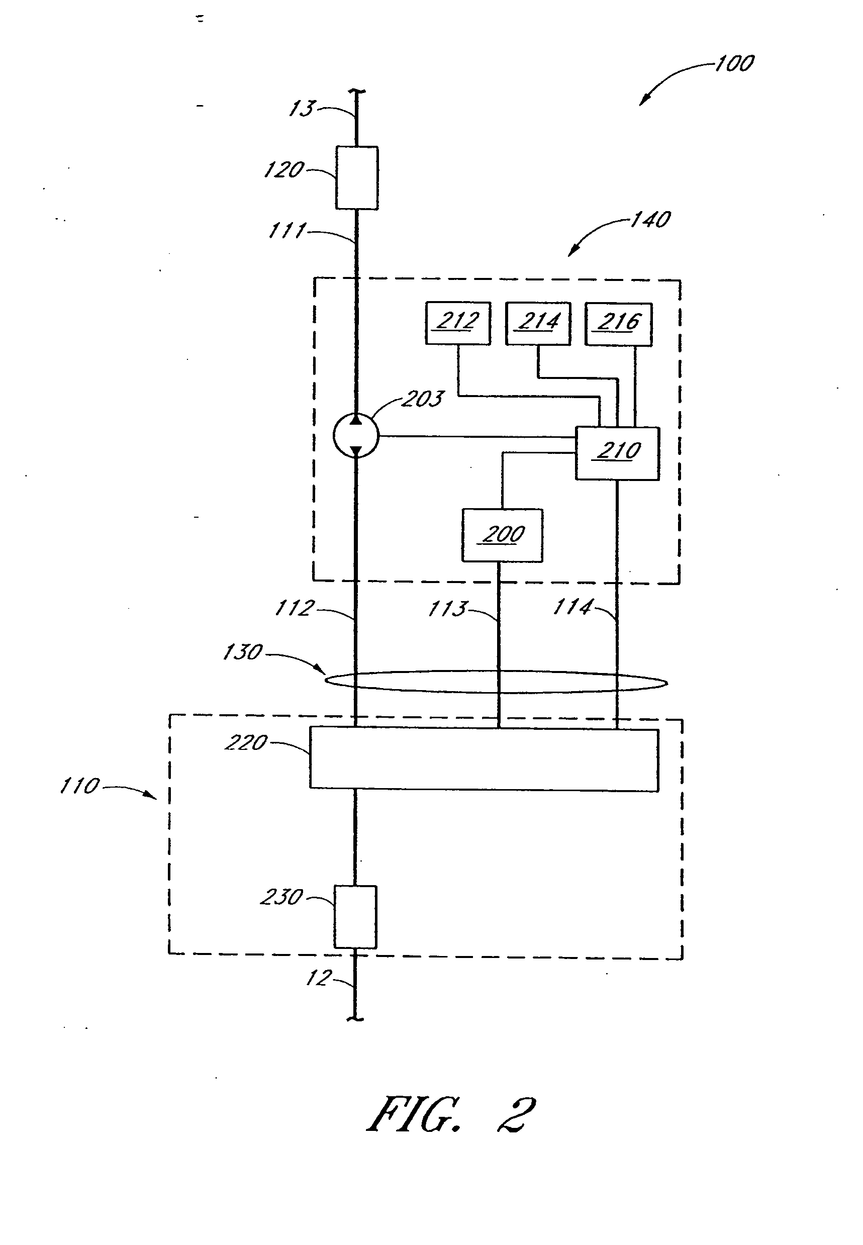
[0143]FIG. 8 is a perspective front view of a sampling system 800 which may be generally similar to sampling system 100, 300 or 500 and the embodiments illustrated in FIGS. 1 through 7, except as further detailed below. The fluid handling and analysis apparatus 140 of sampling system 800 includes the combination of an instrument 810 and a sampling system cassette 820. FIG. 8 illustrates instrument 810 and cassette 820 partially removed from each other. Instrument 810 includes controller 210 (not shown), display 141 and input devices 143, a cassette interface 811, and lines 114. Cassette 820 includes passageway 111 which extends from connector 120 to connector 230, and further includes passageway 113, a junction 829 of passageways 111 and 113, an instrument interface 821, a front surface 823, an inlet 825 for passageway 111, and an inlet 827 for passageways 111 and 113. In addition, sampling assembly 220 is formed from a sampling assembly instrument portion 813 having an opening 815 ...
first embodiment
[0149] In other embodiments, a pair of pinch valve pinchers acts to switch flow between one of two branches of a passageway. FIGS. 13A and 13B are front view and sectional view, respectively, of a pinch valve 1300 in an open configuration that can direct flow either one or both of two branches, or legs, of a passageway. Pinch valve 1300 includes two separately controllable pinch valves acting on a “Y” shaped passageway 1310 to allow switch of fluid between various legs. In particular, the internal surface of passageway 1310 forms a first leg 1311 having a flexible pinch region 1312, a second leg 1313 having a flexible pinch region 1314, and a third leg 1315 that joins the first and second legs at an intersection 1317. A first pair of pinch valve pinchers 1320 is positioned about pinch region 1312 and a second pair of pinch valve pinchers 1330 is positioned about pinch region 1314. Each pair of pinch valve pinchers 1320 and 1330 is positioned on opposite sides of their corresponding ...
second embodiment
[0152]FIGS. 14A and 14B are various views of a second embodiment pinch valve 1400, where FIG. 14A is a front view and FIG. 14B is a sectional view showing one valve in a closed position. Pinch valve 1400 differs from pinch valve 1300 in that the pairs of pinch valve pinchers 1320 and 1330 are replaced by pinchers 1420 and 1430, respectively, that are aligned with passageway 1310.
[0153] Alternative embodiment of pinch valves includes 2, 3, 4, or more passageway segment that meet at a common junction, with pinchers located at one or more passageways near the junction.
[0154]FIGS. 11 and 12 illustrate various embodiment of connector 230 which may also form or be attached to disposable portions of cassette 820 as one embodiment of an arterial patient connector 1100 and one embodiment a venous patient connector 1200. Connectors 1100 and 1200 may be generally similar to the embodiment illustrated in FIGS. 1-10, except as further detailed below.
[0155] As shown in FIG. 11, arterial patient...
PUM
| Property | Measurement | Unit |
|---|---|---|
| length | aaaaa | aaaaa |
| length | aaaaa | aaaaa |
| length | aaaaa | aaaaa |
Abstract
Description
Claims
Application Information
 - R&D Engineer
- R&D Manager
- IP Professional
- Industry Leading Data Capabilities
- Powerful AI technology
- Patent DNA Extraction
Browse by: Latest US Patents, China's latest patents, Technical Efficacy Thesaurus, Application Domain, Technology Topic.
© 2024 PatSnap. All rights reserved.Legal|Privacy policy|Modern Slavery Act Transparency Statement|Sitemap