Striking plate for golf club head

a golf club head and strike plate technology, applied in the field of strike plates, can solve the problems of shortening the life of the golf club head, and achieve the effect of improving the vibration resistan

Inactive Publication Date: 2006-12-28
NELSON PRECISION CASTING
View PDF27 Cites 38 Cited by
  • Summary
  • Abstract
  • Description
  • Claims
  • Application Information

AI Technical Summary

Benefits of technology

[0007] An object of the present invention is to provide a golf club head with improved vibration resistance.
[0009] In accordance with an aspect of the present invention, a golf club head comprises a body and a striking plate mounted to the body. The body comprises a coupling section at a front side thereof. The striking plate comprises a striking portion for striking a golf ball and a perimeter wall extending rearward along a perimeter edge of the striking portion. The perimeter wall comprises an end portion for coupling with the coupling section of the body. At least one reinforcing protrusion is formed on an inner face of the perimeter wall for improving vibration resistance of the body and the striking plate. Preferably, the perimeter wall has a width that varies along a perimeter length thereof.
[0010] In accordance with another aspect of the invention, a golf club head comprises a body and a striking plate mounted to the body. The body comprises a coupling section at a front side thereof. The striking plate comprises a striking portion for striking a golf ball and a perimeter wall extending rearward along a perimeter edge of the striking portion. The perimeter wall comprises an end portion for coupling with the coupling section of the body. The perimeter wall includes a width that varies along a perimeter length thereof for improving elastic deformability of a sweet spot of the striking portion.

Problems solved by technology

As a result, the striking plate 20 might be disengaged or damaged and the life of the golf club head is shortened.

Method used


Image

  • Striking plate for golf club head
  • Striking plate for golf club head
  • Striking plate for golf club head

Examples


first embodiment

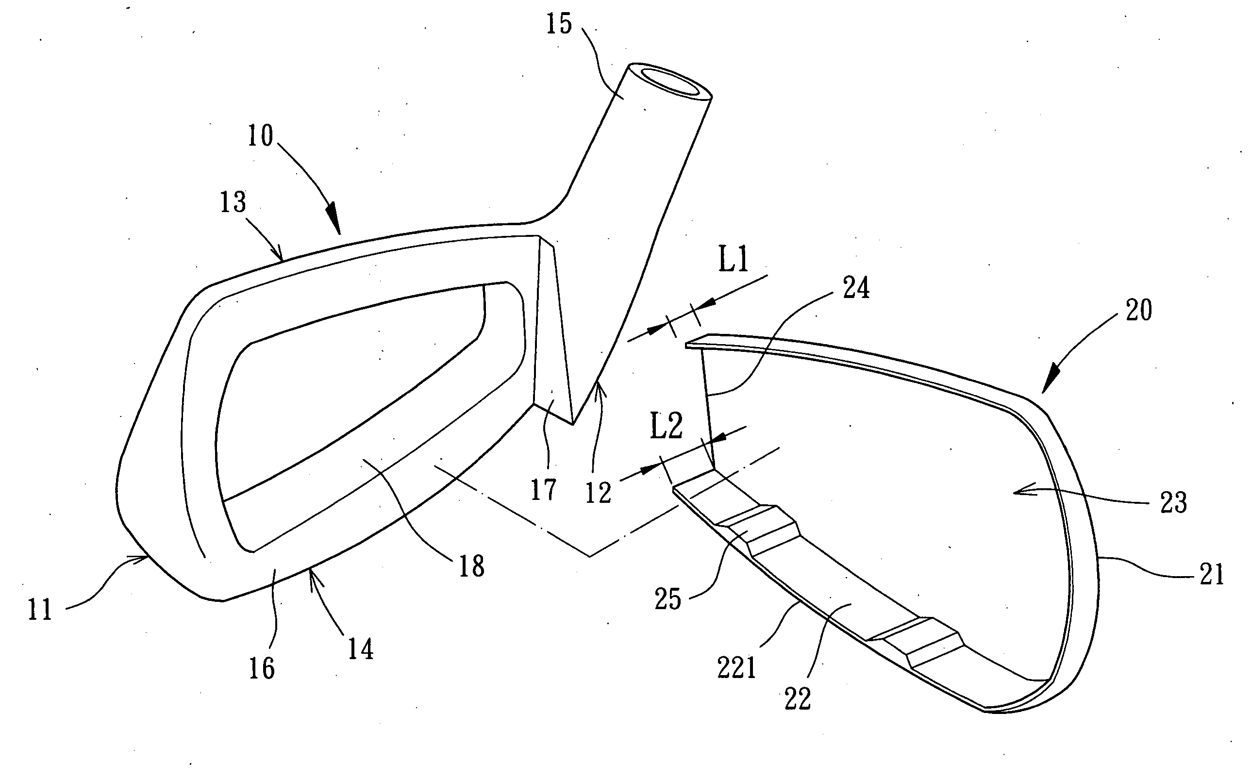
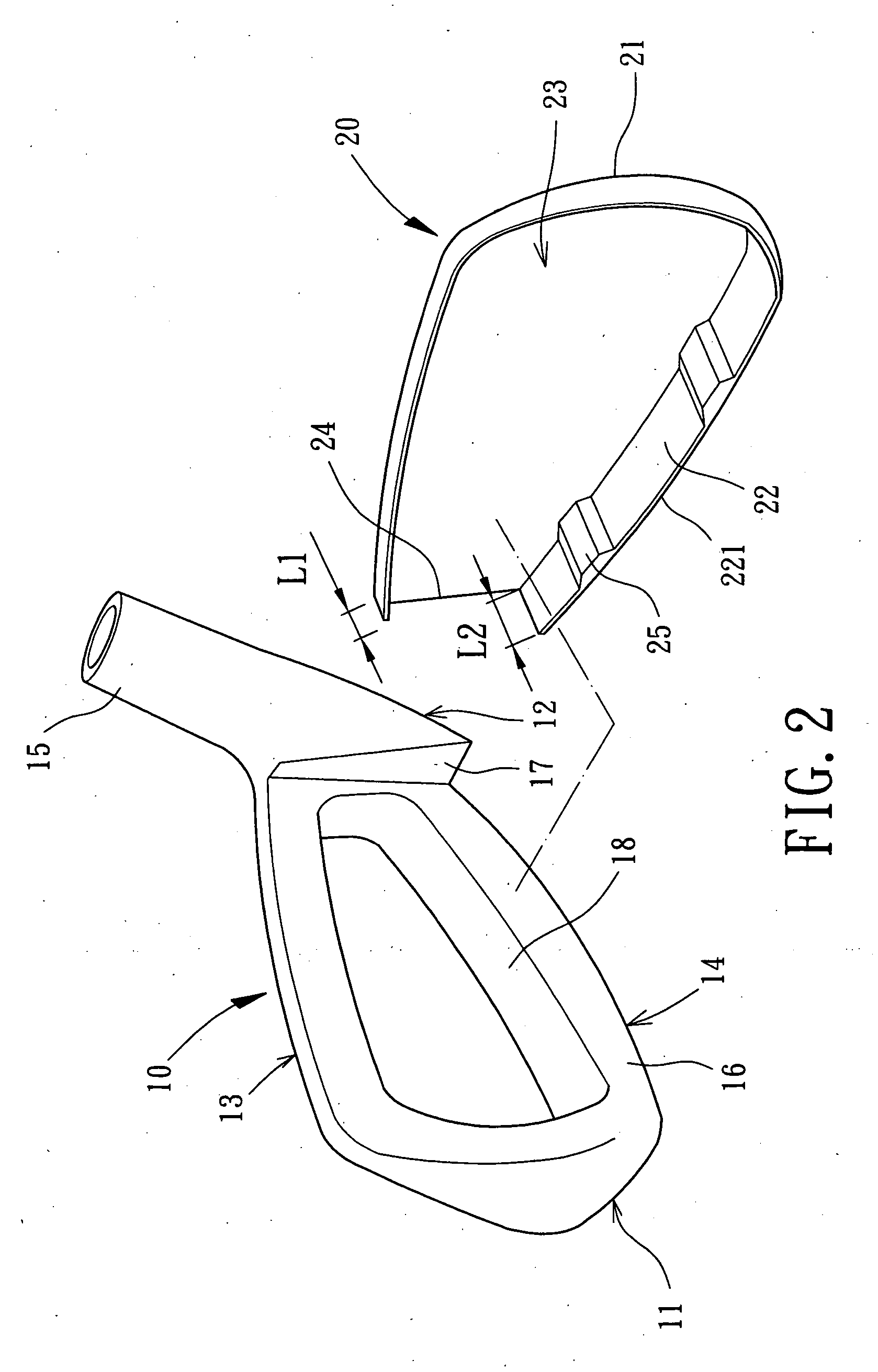
[0025]FIG. 2 shows a golf club head with a striking plate in accordance with the present invention. The golf club head comprises a body 10 and a striking plate 20. In the illustrated embodiment, the golf club head is of iron type. Nevertheless, the striking plate 20 in accordance with the present invention can be used with golf club heads of other types, such as wood type, utility type, putter type, etc.

[0026] Still referring to FIG. 2, the body 10 is preferably made of metal, alloy, or non-metal material and formed by casting, forging, or mechanic processing. The body 10 comprises a toe 11, a heel 12, a crown (or blade) 13, and a sole 14. A hosel 15 is formed on a side of the body 10 for coupling with a shaft (not shown). The body 10 further comprises a coupling section 16 and a sidewall portion 17. Preferably, the body 10 further comprises a cavity 18 having an open or closed end. The coupling section 16 is substantially a front perimeter face on a front side of the body 10. The s...

second embodiment

[0034]FIG. 4 illustrates the striking plate 20 in accordance with the present invention, wherein the striking plate 20 is used with a wood type golf club head. Similarly, the perimeter wall 22 with varied width provides the sweet spot of the striking portion 22 with improved elastic deformability, whereas the reinforcing protrusions 25 effectively avoid cracking of the sidewall 22 or the welding bead, thereby preventing the striking plate 20 from being disengaged or damaged. The vibration resistance of the golf club head is improved and the life of the golf club head is prolonged.

[0035]FIG. 5 illustrates a third embodiment modified from the first embodiment. In this embodiment, two reinforcing protrusions 25 are formed on the inner face of the top portion of the perimeter wall 22 and located adjacent to the toe 11 or the heel 12. The reinforcing protrusions 25 effectively avoid cracking of the sidewall 22 or the welding bead, thereby preventing the striking plate 20 from being disen...


PUM


Abstract

A golf club head includes a body and a striking plate mounted to the body. The body includes a coupling section at a front side thereof. The striking plate includes a striking portion for striking a golf ball and a perimeter wall extending rearward along a perimeter edge of the striking portion. The perimeter wall includes an end portion for coupling with the coupling section of the body. At least one reinforcing protrusion is formed on an inner face of the perimeter wall for improving vibration resistance of the body and the striking plate.

Description

BACKGROUND OF THE INVENTION [0001] 1. Field of the Invention [0002] The present invention relates to a striking plate. In particular, the present invention relates to a striking plate for a golf club head. [0003] 2. Description of Related Art [0004] U.S. Pat. No. 6,506,129 (corresponding Taiwan Utility Model Publication No. 557806) discloses a golf club head capable of enlarging a flexible area of a ball-hitting face thereof. As illustrated in FIG. 1 of the drawings, the golf club head comprises a body 10 and a striking plate 20. The body 10 comprises a toe 11, a heel 12, a crown (or blade) 13, a sole 14, a hosel 15, and a coupling section 16. The coupling section 16 is formed along a perimeter of a front side of the body 10. The striking plate 20 includes a striking face 21 and a perimeter wall 22 bent rearward along a perimeter edge of the striking face 21. The striking plate 20 is thus U-shaped in section. An end portion 221 of the perimeter wall 22 of the striking plate 20 is en...

Claims


Application Information

Patent Timeline
Patent Type & Authority Applications(United States)
IPC IPC(8): A63B53/00
CPCA63B53/0466A63B53/047A63B2053/045A63B2053/0416A63B53/0487A63B53/0416A63B53/045
Inventor HOU, WEN-CHING
Owner NELSON PRECISION CASTING
Why Eureka
Try Eureka