Optical pickup

a technology of optical pickups and pickups, applied in the field of optical pickups, can solve the problems of reducing mass productivity, reducing assembly ease, and affecting the performance of writing and reading on the disk, so as to improve the vibration resistance and/or servo performance of the element, and reduce the cost of assembly

Inactive Publication Date: 2008-12-09
FUNAI ELECTRIC CO LTD
View PDF11 Cites 0 Cited by
  • Summary
  • Abstract
  • Description
  • Claims
  • Application Information

AI Technical Summary

Benefits of technology

[0013]The present invention has been made in view of the above-described circumstances, and an object thereof is to provide an optical pickup with improved vibration resistance without causing a reduction in ease of assembly and thereby a decrease mass productivity or degrading the servo performance of the optical pickup.

Problems solved by technology

In the case of ensuring such a clearance δ between the secondary bearing part 3 and the secondary shaft 102 for the purpose of improving the ease of assembly, etc. as in the comparative example described with reference to FIG. 4, when the optical pickup is vibrated due to external vibration, the existence of the clearance δ may impair the positional relationship between the optical pickup and a disk that is placed and rotated on the turntable, resulting in a possibility of exerting a negative impact on the performance in writing and reading with respect to the disk.
The increase in parts results in a reduction in ease of assembly and thereby decreases mass productivity.
In addition, under the effect of weight increase due to the increase in the number of parts, the servo performance (e.g. traveling stability) of the optical pickup may possibly be reduced.
Therefore, even if the techniques described in the patent documents may be used, it is impossible to improve the vibration resistance without causing a reduction in ease of assembly and thereby decreasing mass productivity or degrading the servo performance of the optical pickup.

Method used


Image

  • Optical pickup
  • Optical pickup
  • Optical pickup

Examples


Embodiment Construction

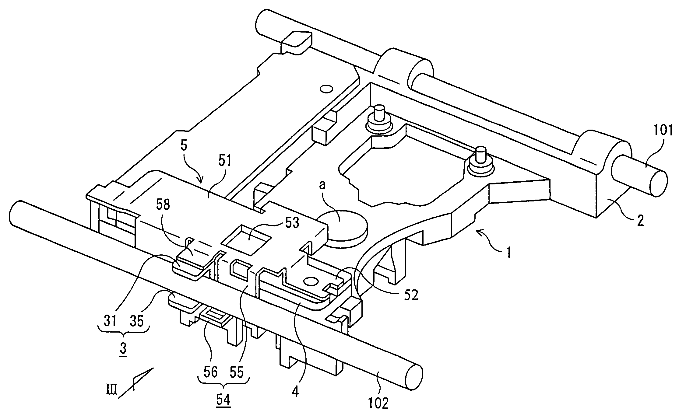
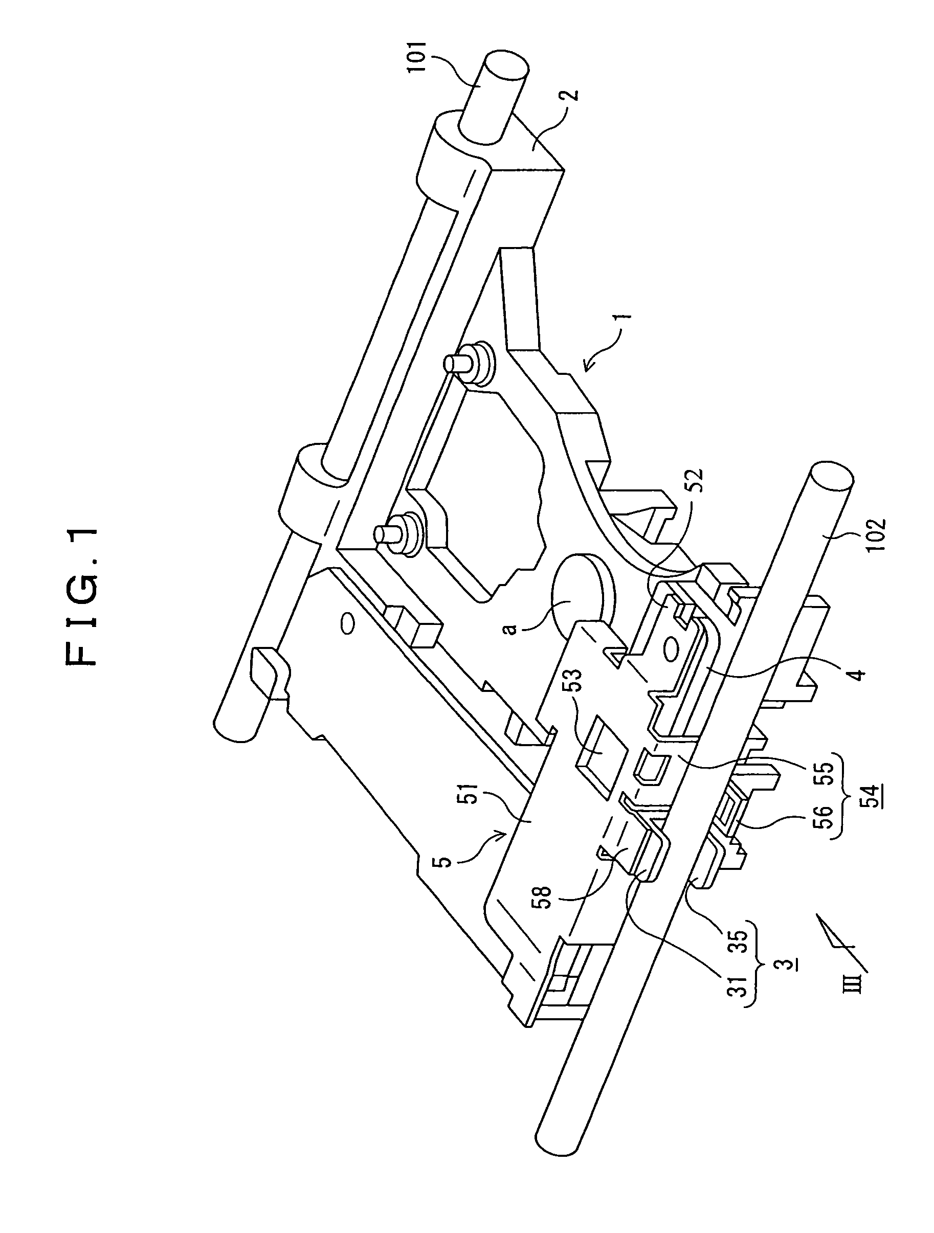
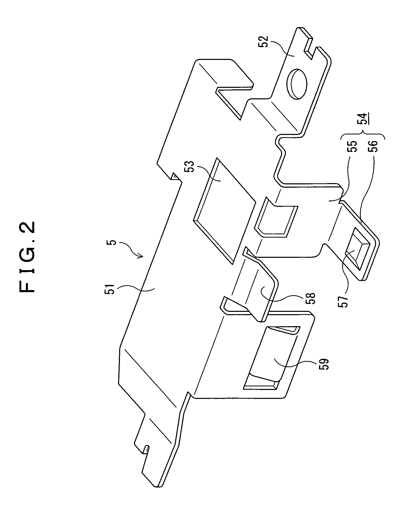
[0026]FIG. 1 is a schematic perspective view of a base member 1 of an optical pickup according to an embodiment of the present invention; FIG. 2 is a perspective view of a radiator plate 5; and FIG. 3 is an enlarged side elevational view when viewed along the arrow III in FIG. 1.

[0027]The present embodiment corresponds to a case where a radiator plate 5 is added to the base member 1 as a comparative example having the arrangement described with reference to FIG. 4. Therefore, the base member 1 is a die-cast product. Also, there are provided a sliding bearing 2 adapted to be guided by a metal main shaft 101 that is attached to a traverse chassis (not shown in the figure) and a secondary bearing part 3 supported slidably by a secondary shaft 102 that is attached to the traverse chassis, respectively, on one side and the other side with respect to an optical axis, passing point “a”, in approximately the central part of the member. Then, the sliding bearing 2 is fitted slidably to the m...


PUM

PropertyMeasurementUnit
temperaturesaaaaaaaaaa
elasticaaaaaaaaaa
weightaaaaaaaaaa

Abstract

An optical pickup with improved vibration resistance and heat dissipation is mounted astride a main shaft 101 and a secondary shaft 102. The travel of the optical pickup is adapted to be guided by the main shaft, where a secondary bearing part 3 adapted to slide relative to the secondary shaft 102 includes an overlapping sliding face 32 and an auxiliary overlapping face 36, and a clearance δ is formed between the auxiliary overlapping face 36 and the secondary shaft 102 to improve ease of assembly. A control element 41 is mounted on a printed circuit board 4 mounted on a base member 1, and the control element is overlapped with a radiator plate 5. The radiator plate 5 is provided with a pressing piece 54, and the pressing piece 54 is brought into elastic contact with the secondary shaft 102 to reliably bring the overlapping sliding face 32 into elastic contact with the secondary shaft 102.

Description

BACKGROUND OF THE INVENTION[0001]1. Field of the Invention[0002]The present invention relates to an optical pickup, and more particularly to an optical pickup in which a control element as a heating part and a radiator plate are mounted on a base member with the travel thereof being adapted to be guided by a main shaft and a secondary shaft.[0003]2. Description of the Prior Art[0004]There have conventionally been proposed various kinds of optical pickups for making recording onto and / or reproduction from a disk as a recording medium (refer to Japanese Patent Laid-Open Publication Nos. 2000-67457 and 2001-307371 for example).[0005]Japanese Patent Laid-Open Publication No. 2000-67457 includes descriptions of, for example, techniques for: passing guide shafts through a guide hole and a U-shaped guide portion provided, respectively, in two parts on the left and the right of a frame so that the frame can be moved in the radial direction of an optical recording disk; mounting a light sour...

Claims


Application Information

Patent Timeline
Patent Type & Authority Patents(United States)
IPC IPC(8): G11B7/00
CPCG11B7/08582G11B33/1426
Inventor NISHIDATE, TETSUOMURAKAMI, TAKAYUKI
Owner FUNAI ELECTRIC CO LTD
Why Eureka
Try Eureka