
Electric compressor

a compressor and electric technology, applied in the direction of positive displacement liquid engines, piston pumps, liquid fuel engines, etc., can solve the problems of unsatisfactory vibration resistance and inability to completely prevent the displacement of electronic components from the board, and achieve the effect of improving vibration resistance and reducing nois

Active Publication Date: 2020-07-02
TOYOTA IND CORP
View PDF0 Cites 0 Cited by
  • Summary
  • Abstract
  • Description
  • Claims
  • Application Information

AI Technical Summary

Benefits of technology

The technical effect of this patent is to create an electric compressor with an inverter that has better resistance to vibration and less noise.

Problems solved by technology

Accordingly, the relative displacement of the electronic components from the board cannot be fully prevented, thus exhibiting unsatisfactory vibration resistance.

Method used


Image

  • Electric compressor
  • Electric compressor
  • Electric compressor

Examples


Embodiment Construction

[0012]An embodiment of the present disclosure will now be described with reference to the drawings. In the drawings referred to hereinafter, identical or corresponding parts are denoted by identical reference numbers.

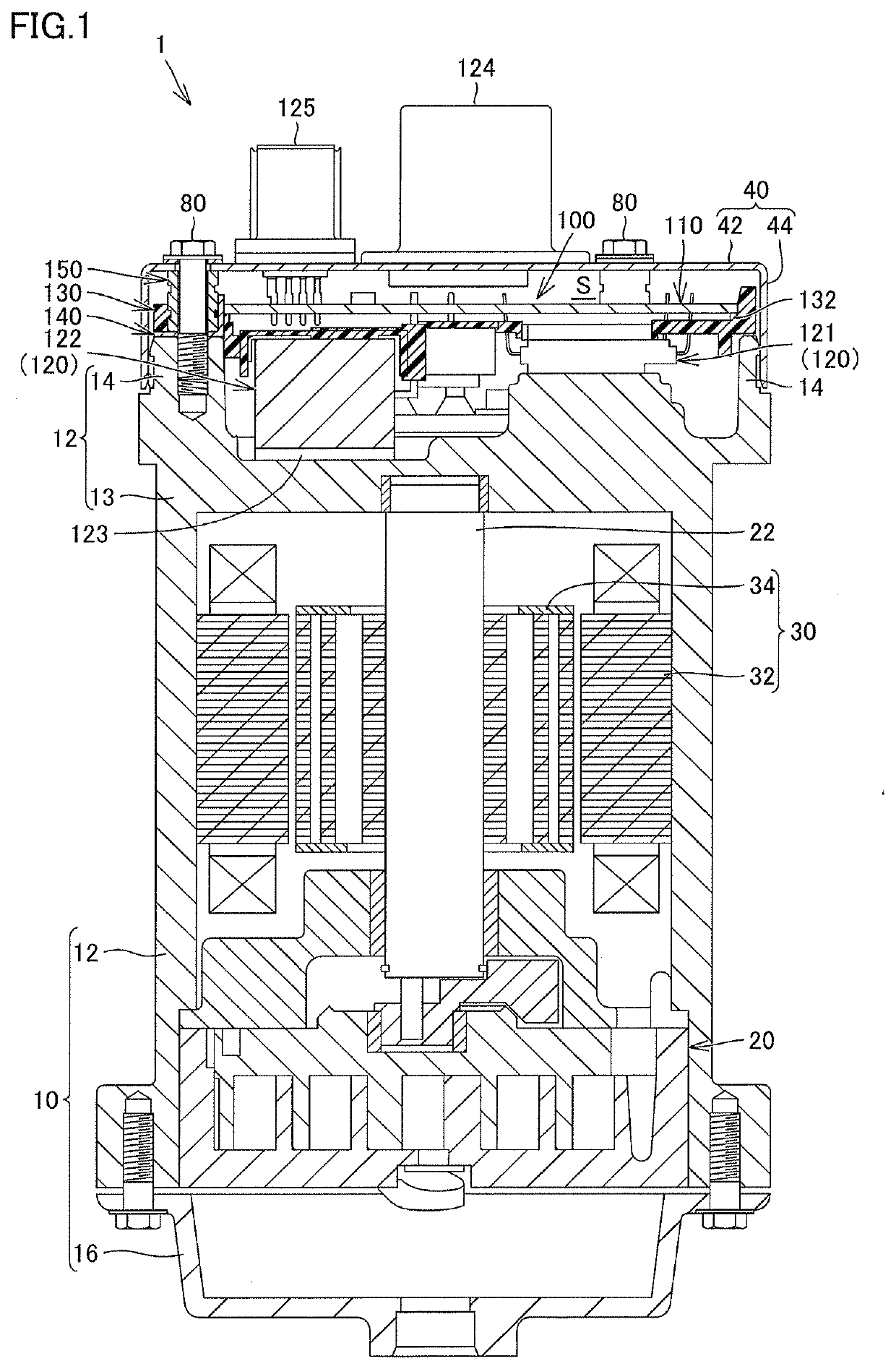
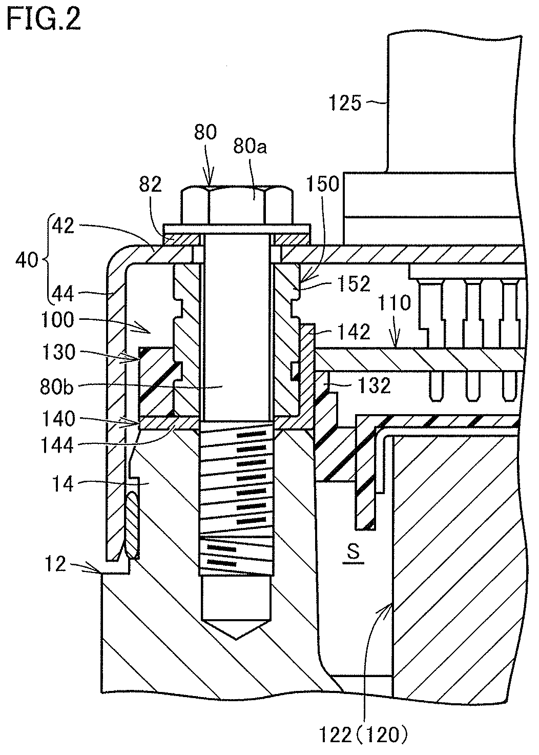
[0013]FIG. 1 is a cross-sectional view schematically showing an electric compressor in an embodiment of the present disclosure. FIG. 2 schematically shows a part around a bus bar and a tubular member of the electric compressor shown in FIG. 1. An electric compressor 1 in the present embodiment is used for, for example, an air conditioner for a vehicle.

[0014]As shown in FIG. 1 and FIG. 2, the electric compressor 1 includes a housing 10, a compression mechanism 20, a motor 30, a cover 40, at least one fastener 80, and an inverter 100.

[0015]The housing 10 contains the compression mechanism 20 and the motor 30. The housing 10 is composed of an electrically conductive material (e.g., aluminum). The housing 10 includes a motor housing 12 and a discharge housing 16.

[0016]The m...


PUM


Abstract

An electric compressor includes a motor housing, an inverter, a cover, and a fastener. The inverter includes a board; an electronic component; a holder composed of an insulating material, the holder containing the electronic component and supporting the board; a bus bar integrated with the holder, and electrically connected to a circuit pattern and the motor housing; and a tubular member interposed between the cover and the bus bar, with the fastener inserted in the tubular member. The fastening force from the fastener causes the tubular member to press the bus bar toward the motor housing.

Description

[0001]This nonprovisional application is based on Japanese Patent Application No. 2018-244242 filed on Dec. 27, 2018 with the Japan Patent Office, the entire contents of which are hereby incorporated by reference.BACKGROUND[0002]The present disclosure relates to an electric compressor.DESCRIPTION OF THE BACKGROUND ART[0003]Electric compressors for use in air conditioners of vehicles have been known. For example, Japanese Patent Laying-Open No. 2004-228126 discloses an electric compressor in which a circuit board is disposed on a frame resin member having an insert-molded shield and the resin member is assembled with a motor housing, so that the shield electrically connects the ground pattern on the circuit board to the motor housing.SUMMARY[0004]In the electric compressor described in Japanese Patent Laying-Open No. 2004-228126, electronic components mounted on the circuit board, such as a power transistor and a capacitor, are disposed in contact with the outer periphery of the moto...

Claims


Application Information

Patent Timeline
Patent Type & Authority Applications(United States)
IPC IPC(8): H02K5/24H02K3/50H02K7/14H02K11/33B60H1/32
CPCH02K2203/09B60H2001/006B60H1/3222H02K11/33H02K2207/03H02K7/14H02K5/24H02K2211/03H02K3/50H02K5/04H02M1/00F04B39/0027F04B35/04H02K5/225F04C23/02F04C29/0085H05K7/1432F04C2240/403F04C2240/30F05B2260/30
Inventor KINOSHITA, YUSUKEENAMI, SHINGOYANO, JUNYA
Owner TOYOTA IND CORP
Learn More