Compressor, air conditioning system and vehicle

a compressor and air conditioning technology, applied in the field of compressors, can solve the problems of increasing the complexity of the air conditioning system with an enthalpy increasing system, hardly meeting the requirement for ultra-low temperature rapid heating, and the low output efficiency of the battery, so as to improve the reliability of the enthalpy increasing system, reduce the temperature rise in the pipeline, and increase the vibration resistance of the flash structure

Active Publication Date: 2021-08-26
ZHUHAI GREE REFRIGERATION TECH CENT OF ENERGY SAVING & ENVIRONMENTAL PROTECTION
View PDF0 Cites 0 Cited by
  • Summary
  • Abstract
  • Description
  • Claims
  • Application Information

AI Technical Summary

Benefits of technology

[0035]Based on the above technical solutions, the compressor, the air conditioning system and the vehicle provided by the present disclosure have the advantages that the flasher structure is arranged on the compressor body, so that the air conditioning system is simpler and more compact; the gas supply enthalpy increasing pipelines between the flasher and the compressor are reduced, the intermediate cooled gas flashed can quickly enter the compression cavity, and the pressure loss in the intermediate pipeline and the temperature rise in the pipeli

Problems solved by technology

Especially in cold winter, when the external ambient temperature is less than −10° C., the output efficiency of the battery is low.
The conventional compressor hardly meets the requirement for ultra-low temperature rapid heating, so an enthalpy increasing technology is needed.
However, the conventional scroll compressors hardly meet the requirement for ultra-low temperature rapid heating.
Compared with the conventional air conditioning system, the air conditioning system with an enthalpy increasing system is more complex.
Excessive pipeline arrangements in the air conditioning system challenge the endurance of the electric vehicle and the reliability of the system itself

Method used


Image

  • Compressor, air conditioning system and vehicle
  • Compressor, air conditioning system and vehicle
  • Compressor, air conditioning system and vehicle

Examples


Embodiment Construction

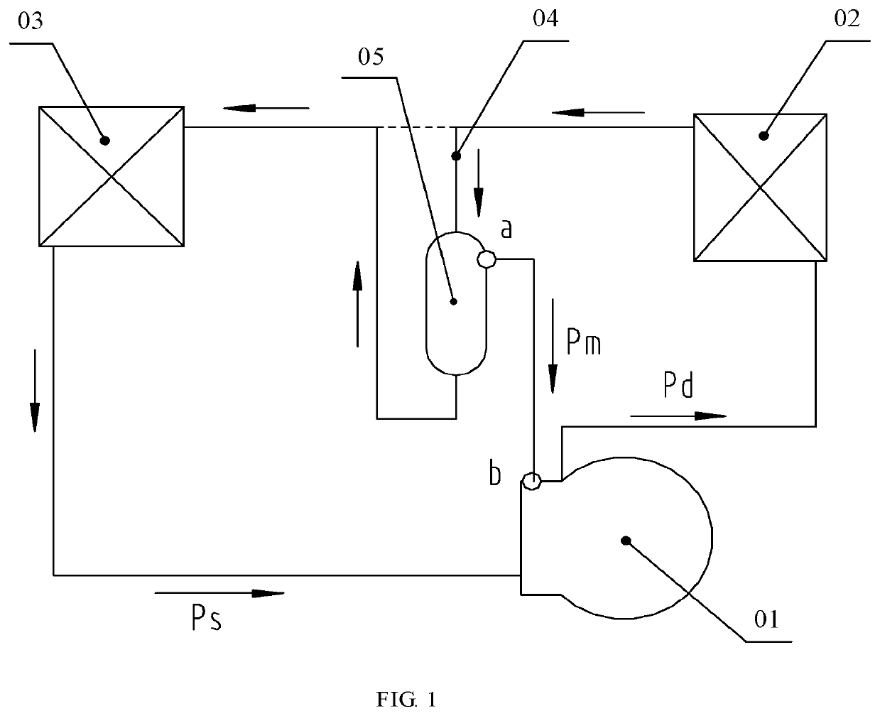
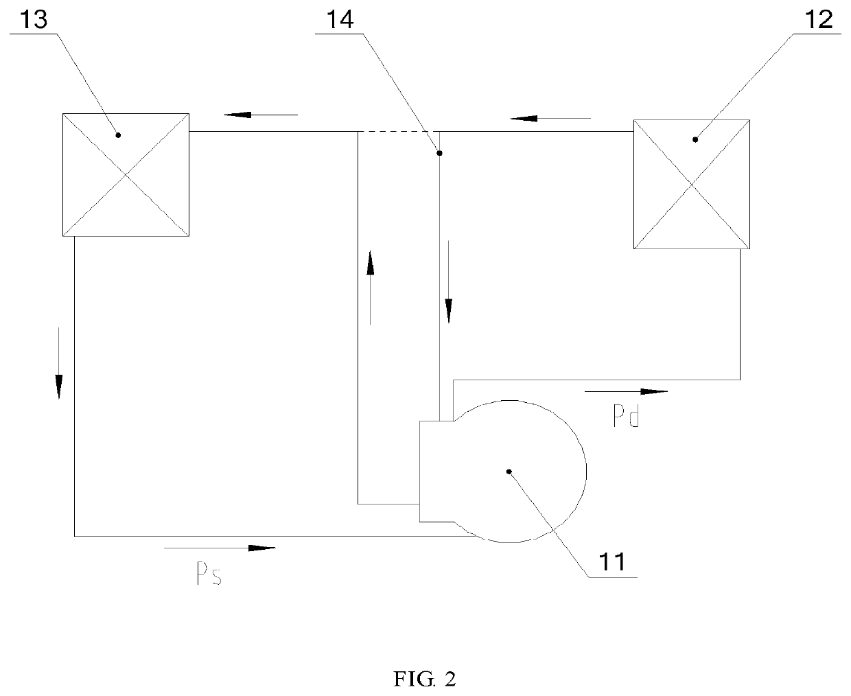
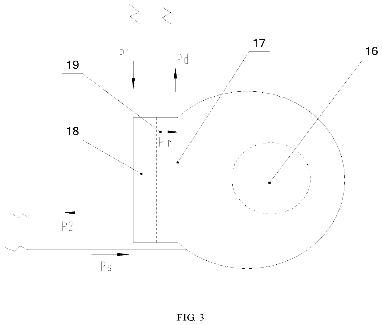
[0060]In order to meet the requirement for ultra-low temperature rapid heating of an air conditioning system for an electric vehicle, the present disclosure proposes an enthalpy increasing air conditioning system that is more suitable for an electric vehicle, where the integrated design of a vehicle-mounted electric compressor and an intermediate cooling flash device simplifies the vehicle-mounted enthalpy increasing air conditioning system and improves the reliability of the system.

[0061]A clear and complete description will be made to the technical solutions in the embodiments of the present disclosure below in combination with the accompanying drawings in the embodiments of the present disclosure. Apparently, the embodiments described are only part of the embodiments of the present disclosure, not all of them. All other embodiments obtained by those of ordinary skill in the art based on the embodiments of the present disclosure without creative efforts shall fall within the prote...


PUM


Abstract

The present disclosure discloses a compressor, an air conditioning system and a vehicle. The compressor comprises a compression cavity, and further comprises a flash cavity capable of flashing a liquid refrigerant, and a communicating passage that communicates a flash cavity gas outlet of the flash cavity and an enthalpy increasing gas supply port of the compression cavity; the flash cavity is provided with an inlet and a liquid outlet, the inlet of the flash cavity is configured to be communicated with an outlet of a condenser, and the liquid outlet of the flash cavity is configured to be communicated with an inlet of an evaporator. The air conditioning system comprises the compressor, the evaporator, the condenser, a flasher, and various pipelines for connecting the entire system. The compressor comprises the flash cavity with a flash function, so that the entire enthalpy increasing system is simpler, the space for an additional flasher structure is saved, and the enthalpy increasing system is more suitable for a vehicle-mounted air conditioning system with a limited space. The present disclosure also discloses a vehicle, particularly an electric vehicle, using the air conditioning system.

Description

FIELD OF THE DISCLOSURE[0001]The present disclosure relates to the technical field of air conditioners, in particular to a compressor, an air conditioning system and a vehicle.BACKGROUND OF THE DISCLOSURE[0002]As new energy vehicles, electric vehicles have the advantages of energy conservation and environmental protection. As an energy-consuming component, the vehicle-mounted air conditioning system therein should achieve rapid cooling and heating and maintain low power consumption. Therefore, the air conditioning system of the electric vehicle requires higher energy efficiency and higher refrigerating and heating capacity of a compressor. Especially in cold winter, when the external ambient temperature is less than −10° C., the output efficiency of the battery is low. In this case, the vehicle-mounted air conditioner needs to achieve rapid heating and maintain high energy efficiency at such a harsh ambient temperature, which imposes higher requirements on the energy efficiency and ...

Claims


Application Information

Patent Timeline
IPC IPC(8): B60H1/32B60H1/00
CPCB60H1/3223B60H1/00392B60H1/00F04C18/02F04C29/00F04C18/0215F04C15/0096F04C19/004F04C29/0007
Inventor LIU, YUNHU, YUSHENGSHAN, CAIXIAKANG, XIAOLI
Owner ZHUHAI GREE REFRIGERATION TECH CENT OF ENERGY SAVING & ENVIRONMENTAL PROTECTION
Why Eureka
Try Eureka