Air-conditioning system with full heat recovery

a technology of air-conditioning system and heat recovery, which is applied in the direction of domestic cooling apparatus, lighting and heating apparatus, heating types, etc., can solve the problems of increasing the popularity of air-conditioners, and affecting the efficiency of air-conditioning systems. , to achieve the effect of reducing the overall temperature of the condensa

Inactive Publication Date: 2007-01-04
LI ZHIMING
View PDF12 Cites 34 Cited by
  • Summary
  • Abstract
  • Description
  • Claims
  • Application Information

AI Technical Summary

Benefits of technology

[0033] The present air-conditioning system with full heat recovery operates as follows: the condenser, expansion valve, evaporator and compressor of the present air-conditioning system with full heat recovery are sequentially connected to form a closed refrigeration circuit. The refrigeration circuit utilizes a coolant (e.g. chlorofluorocarbon) for refrigeration to cool indoor air. During the same time, the cooling fan introduces indoor exhaust air (of lower temperature and relative humidity) and outdoor air from the indoor air outlet and the outdoor air inlet into the space in which the evaporative condenser is located in order to perform heat exchange with the evaporative condenser and with the cooling water that flows through the evaporative condenser. The cooling water transfers heat to the cooling air by transferring heat (sensible heat) to the cooling air and by evaporating water (latent heat) of the cooling air. The temperature of the cooling water decreases and the temperature of the cooling air (indoor exhaust air and outdoor air) increases. Finally, it is discharged from the machine from the exhaust vent through the cooling fan. This efficiently utilizes the cooling energy of air and attains the object of energy saving. In addition, the condensate recycle system can at the same time recycle the condensate of lower temperature and mix it with the condensate in the evaporative condenser, thereby reducing the overall temperature of the condensate. This serves to assist the cooling of the evaporative condenser and effectively uses the cooling energy and saves water.
[0034] The present invention utilizes low temperature, low humidity indoor exhaust air as cooling air for the evaporative condenser. It makes use of the sensible heat (temperature difference) of indoor exhaust air as well as the latent heat (humidity difference) of indoor exhaust air. The condensation effect is much better than directly utilizing outdoor air as cooling air. It prevents energy loss due to air exchange and ventilation and attains prominent energy saving effects when compared with the existing cooling systems. Annual operational costs can be reduced by more than 30%.
[0035] The present invention does not require a condensate discharge system. The present invention directly recycles condensate which is discharged in the existing facilities into the cooling water system as cooling water. Since the temperature of the condensate is low, the cooling energy of the condensate is recycled and better-cooling effects can be attained. Direct recycle of the condensate also prominently saves cooling water consumption of the cooling systems. When compared with cooling systems using cooling towers, the present invention has a very high water-saving efficiency.
[0036] Since indoor exhaust full heat recovery is achieved, the fresh air load of the air-conditioning system is greatly reduced. Volume of fresh air is increased while the cooling load of the system is not significantly increased, thereby effectively improving indoor air quality and making the present invention energy and water saving and healthy in application.
[0037] The present invention does not require a cooling tower or a powerful cooling water pump, thereby lowering engineering costs and energy consumption. When compared with the cooling water systems of existing cooling systems, the present invention can save more than 15% of energy in this regard. Since no cooling tower is required, the water-film spraying of the condenser of the present invention completely eliminates water spillage. Therefore, when compared with other cooling systems using cooling towers, the present invention can attain water saving effects of over 50%.
[0038] The present invention recycles energy to the largest extent and lowers energy and water consumption. It effectively solves the problems of increased energy consumption due to an increase in fresh air volume of air-conditioning systems. It possesses the features of energy and water saving and healthy application. It can be widely used in the air-conditioning systems in restaurants, hospitals, supermarkets, villas, offices and so forth. It has wide applications and good market prospects.

Problems solved by technology

However, the increasing popularity of air-conditioners exerts enormous pressure on the existing insufficient electricity supply facilities.
The operational costs of air-conditioners are huge.
It can be seen that this type of air-conditioners is of high energy consumption.
Nevertheless, since water-cooled air-conditioners are installed additionally with a cooling tower and a cooling pump, the overall energy consumption of the system and the costs of the apparatus increase.
Further, there are relatively strong winds in the cooling tower.
Furthermore, the air-conditioners produce large volume of condensate during the refrigeration process.
In existing air-conditioning systems, fresh air load amounts to around 30% of the total air-conditioning load and the energy consumption is high.
To reduce the total load, fresh air reduction methods are often used, which lead to poorer air quality in the air-conditioning area and fail to satisfy the hygienic requirements.
Its temperature is usually relatively low at 25° C. to 28° C. Its relative humidity is also low at 60% to 70% and its wet-bulb temperature is even as low as 20° C. to 23° C. The existing air-conditioners of air-conditioning systems fail to utilize this cooling energy and thus lead to wastage directly.

Method used


Image

  • Air-conditioning system with full heat recovery
  • Air-conditioning system with full heat recovery
  • Air-conditioning system with full heat recovery

Examples


Embodiment Construction

[0048] The present invention is further described by the following embodiments with the accompanying drawings, but the embodiments should not be regarded as limiting.

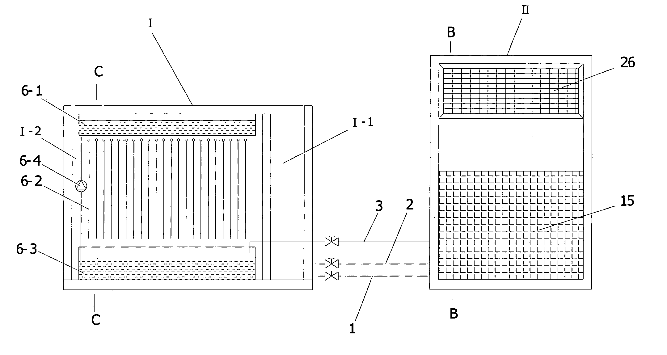
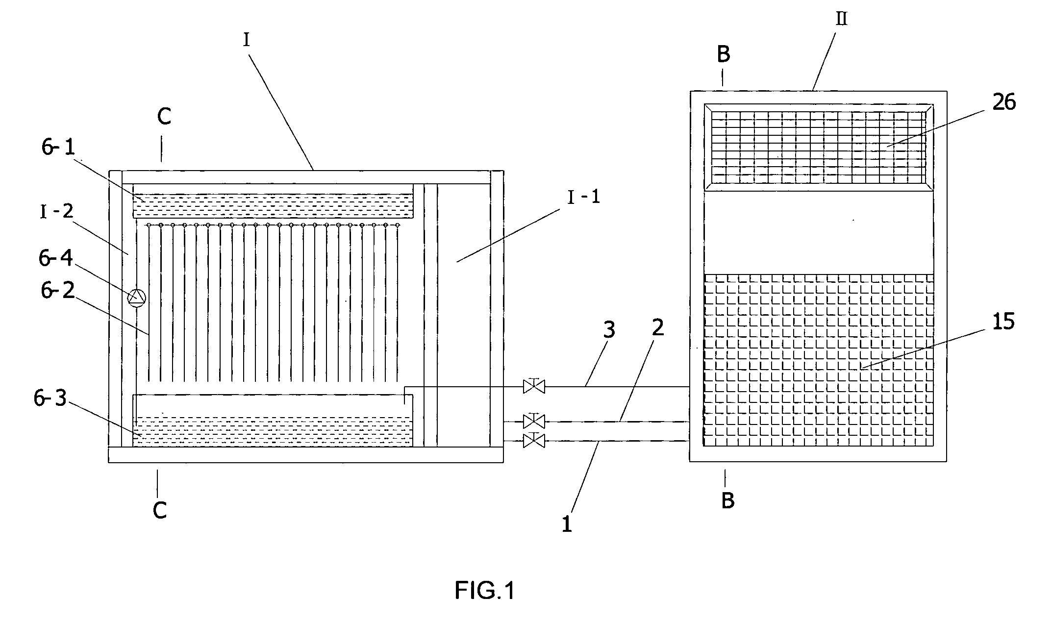
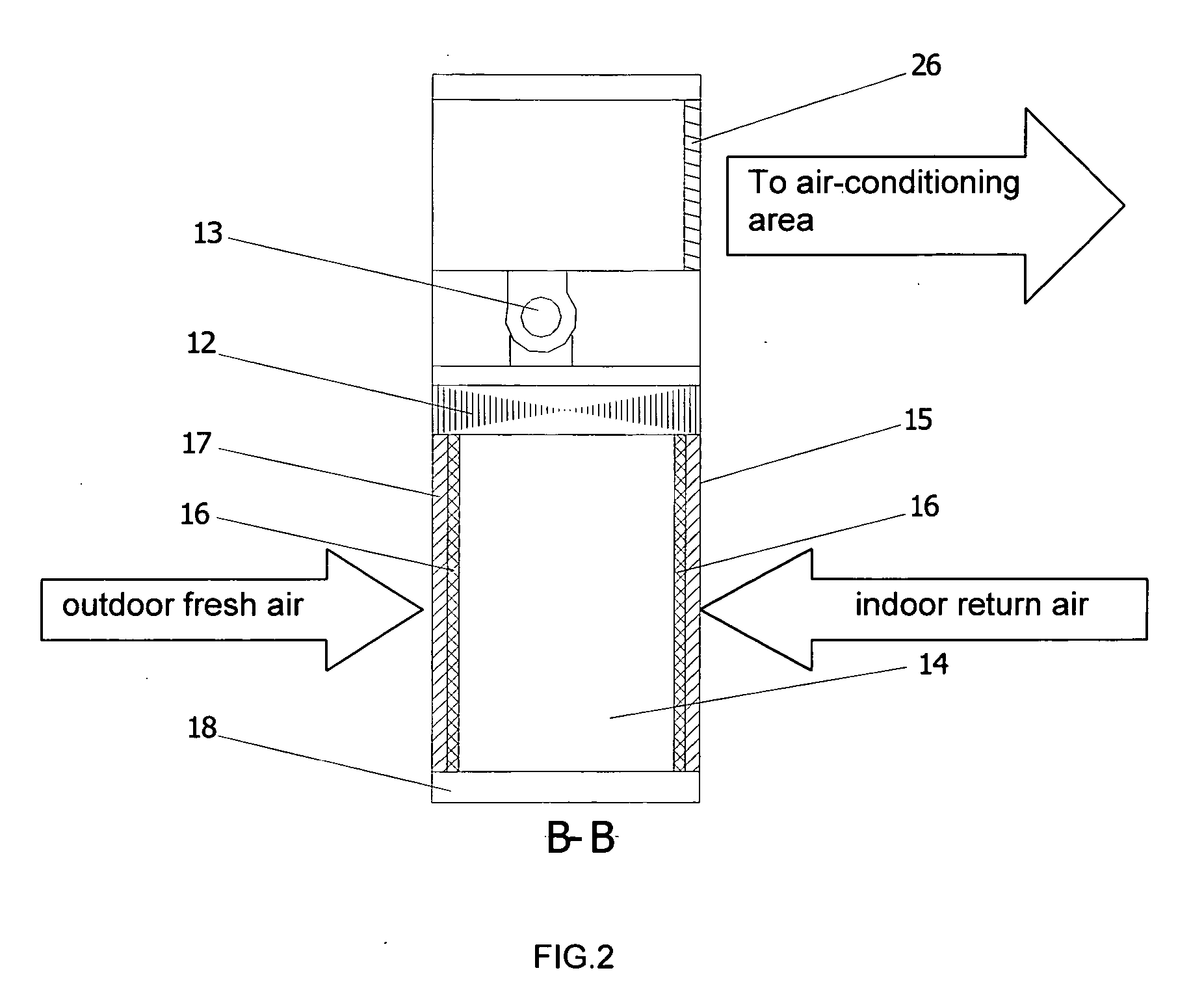
[0049] FIGS. 1 to 4 show the structure of the present invention. The present air-conditioning system with full heat recovery is of a split-type structure with a main unit (outdoor unit) I which cools a terminal (indoor unit) II. As illustrated in FIG. 1, the main unit I and the terminal II are connected through a liquid supply pipe 1, a return air pipe 2 and a condensate recycling pipe 3. FIG. 4 shows the operation of this embodiment. A compressor 4, a one-way valve 5, an evaporative condenser 6, a liquid storage member 7, a drier-filter 8, a liquid mirror 9, a liquid supply electromagnetic valve 10, an expansion valve 11 and a finned evaporator 12 are sequentially connected to form a closed refrigeration circuit, and a coolant (chlorofluorocarbon) flows in the refrigeration circuit to perform refrigeration, wherein th...


PUM


Abstract

The present invention relates to an air-conditioning system with full heat recovery comprising a condenser, an evaporator, a compressor and an expansion valve; one side of the condenser is disposed in a position corresponding to an indoor air outlet and an outdoor air inlet; the other side of the condenser is provided with an exhaust vent; and a cooling fan is disposed between the exhaust vent and a cooling air opening. The present air-conditioning system with full heat recovery can be connected with a condensate recycle system. The present invention utilizes low temperature, low humidity indoor exhaust air as cooling air for the evaporative condenser. It makes use of the sensible heat. (temperature difference) of indoor exhaust air as well as the latent heat (humidity difference) of indoor exhaust air, thereby attaining better condensation effects. It also uses the condensate to assist cooling and increases cooling and water saving effects. The present invention can be widely used in the air-conditioning systems in restaurants, hospitals, supermarkets, villas and offices and has wide applications.

Description

BACKGROUND OF THE INVENTION [0001] The present invention relates to air-conditioning cooling apparatus and more particularly pertains to an air-conditioning system with full heat recovery. [0002] Following the increasing popularity of air-conditioners, the air-conditioning industry has been fast developing in the past decade. However, the increasing popularity of air-conditioners exerts enormous pressure on the existing insufficient electricity supply facilities. Statistics show that electricity consumption-of-air-conditioners amounts to 35% of the total electricity consumption of an office building. The operational costs of air-conditioners are huge. Developing air-conditioning facilities of effective energy saving capability has therefore been a development trend in the air-conditioning industry. [0003] The existing air-conditioners are mainly divided into two types, namely air-cooled air-conditioners and water-cooled air-conditioners. Air-cooled air-conditioners utilize outdoor a...

Claims


Application Information

Patent Timeline
Patent Type & Authority Applications(United States)
IPC IPC(8): F28D5/00F25B39/04F25D3/02
CPCF24F1/0003F24F13/222F24F1/32
Inventor LI, ZHIMING
Owner LI ZHIMING
Why Eureka
Try Eureka