Arrangement for converting thermal energy to mechanical energy in a vehicle

a technology of mechanical energy and thermal energy, which is applied in the direction of machines/engines, braking systems, machine operation modes, etc., can solve the problems of increasing the amount of mechanical energy being created in the turbine, and achieves the effects of reducing the amount of mechanical energy, and increasing the efficiency

Inactive Publication Date: 2013-12-19
SCANIA CV AB
View PDF7 Cites 10 Cited by
  • Summary
  • Abstract
  • Description
  • Claims
  • Application Information

AI Technical Summary

Benefits of technology

[0006]The arrangement comprises substantially the same components as a conventional WHR system in a vehicle. A conventional WHR system can produce mechanical energy from a working medium which is warmed by a heat source so that it vaporises and is extra-heated. The working medium is then expanded in a turbine so that mechanical energy is created. The amount of mechanical energy which can be created in such a system depends mainly on the temperature to which the working medium is extra-heated in the evaporator and on the condensation temperature which the working medium assumes when it condenses in a condenser in the system. According to the invention, at times when the vehicle requires extra propulsive force, the cold refrigerant is used to cool the working medium after it has been cooled in the system's condenser. This combines with suitable adjustment of the amount of working medium in the line circuit to cause the working medium to assume a lower condensation temperature. This leads to the possibility of a larger amount of mechanical energy being created in the turbine at times when the vehicle requires extra propulsive force. The arrangement may for example recover and store brake energy when the vehicle is travelling downhill, and use this energy when travelling uphill The arrangement thus achieves greater efficiency than a conventional WHR system in which the vehicle's braking energy is not recovered.
[0007]According to the present invention, the arrangement comprises a space for storing the refrigerant when it has been cooled by the cooling system. This space may with advantage be thermally insulated to enable the refrigerant to maintain its low temperature. The lower the temperature of the refrigerant, the more effectively it can lower the condensation temperature of the working medium in the line circuit and increase the production of mechanical energy in the turbine. The arrangement may comprise a heat exchanger situated at a location downstream of the condenser in the line circuit, a refrigerant circuit which has an extent between the storage space and the heat exchanger, and a pump adapted to being activated by the control unit to circulate the refrigerant from the storage space to the heat exchanger in which it cools the working medium at times when the vehicle is to be braked. In this case the cold refrigerant is led from the storage space to a heat exchanger, in which it subjects the working medium to an extra step of cooling. The refrigerant circuit then leads the refrigerant back to the storage space. Alternatively, the arrangement may comprise a valve situated at a location downstream of the condenser in the line circuit and an extra line loop which has an extent between the valve and the storage space, in which case the control unit is adapted to putting the valve into a position whereby the working medium is led from the valve to the storage space, in which it is cooled by the cold refrigerant at times when the vehicle is to be provided with extra propulsive force. When it has undergone an extra step of cooling by the refrigerant, the working medium is led back to the line circuit at a location upstream of the evaporator.
[0008]According to an embodiment of the invention, the refrigerant takes the form of a mixture of water and glycol. Mixing water and glycol in suitable amounts makes it possible to obtain a coolant which has a very low freezing temperature. Such a coolant mixture can be cooled to a temperature far below 0° C. without freezing. Alternatively, the refrigerant may take the form of material which has the characteristic of changing phase from liquid state to solid state in the storage space when it is cooled by the cooling system. Large amounts of thermal energy may be stored in phase-convertible material. This means that relatively small amounts of refrigerant will effect good cooling of the working medium when it undergoes the extra step of cooling. A refrigerant which changes phase requires relatively little storage space.
[0009]According to a preferred embodiment of the invention, the control unit is adapted to receiving information from a sensor which monitors a parameter related to the position of a brake control in the vehicle and, when the brake control is in a position which indicates that the vehicle is to be braked, to connecting the cooling system to the vehicle's power train. Such a brake control may be a control by which a driver initiates an automatic braking process of the vehicle to achieve a desired constant speed downhill. Heavy vehicles usually have one or more supplementary brakes by which they are braked downhill to prevent wear on and overloading of their wheel brakes. In this case the cooling system may replace such a supplementary brake. The brake control may alternatively be a conventional brake pedal.

Problems solved by technology

This leads to the possibility of a larger amount of mechanical energy being created in the turbine at times when the vehicle requires extra propulsive force.

Method used


Image

  • Arrangement for converting thermal energy to mechanical energy in a vehicle
  • Arrangement for converting thermal energy to mechanical energy in a vehicle
  • Arrangement for converting thermal energy to mechanical energy in a vehicle

Examples


Embodiment Construction

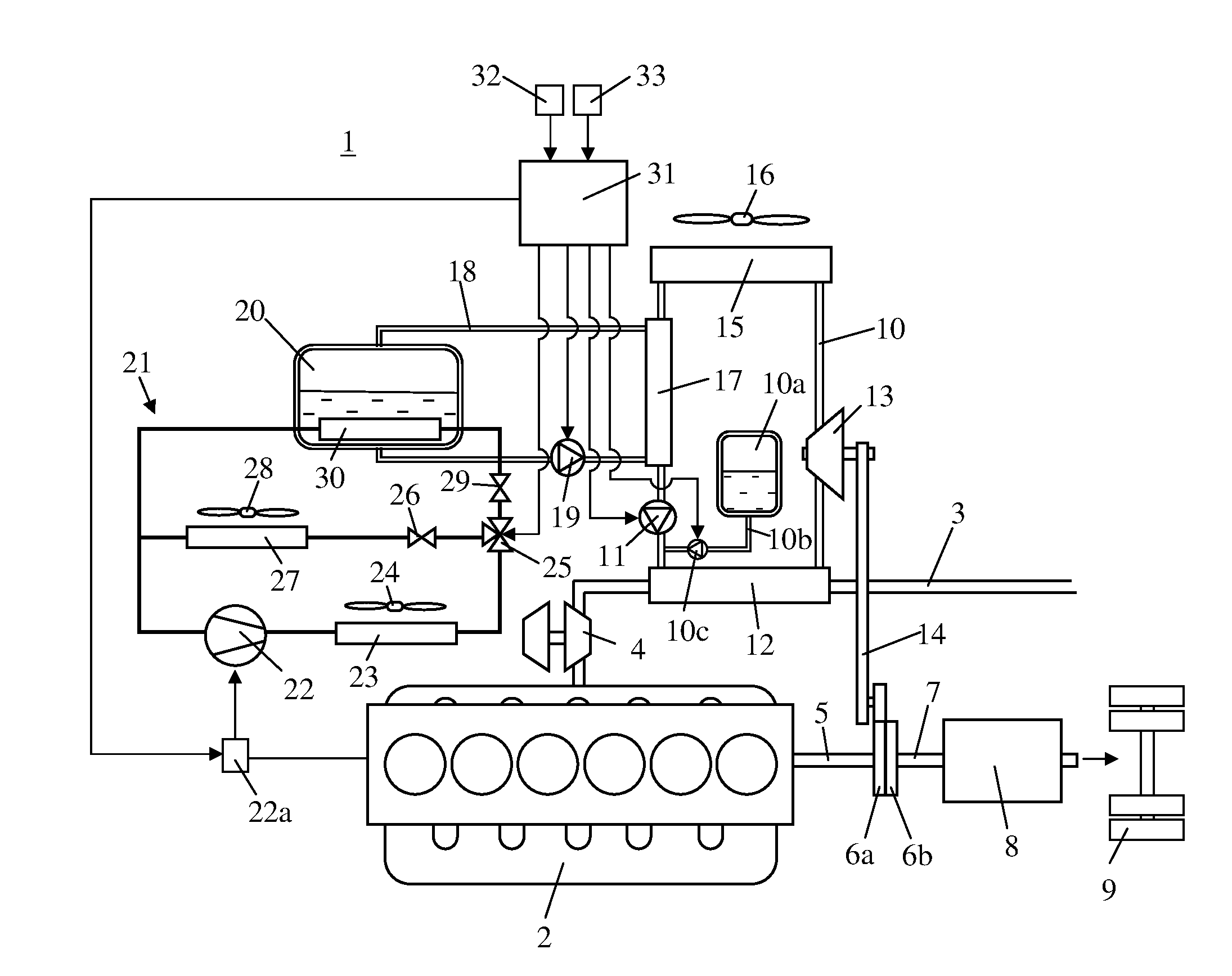
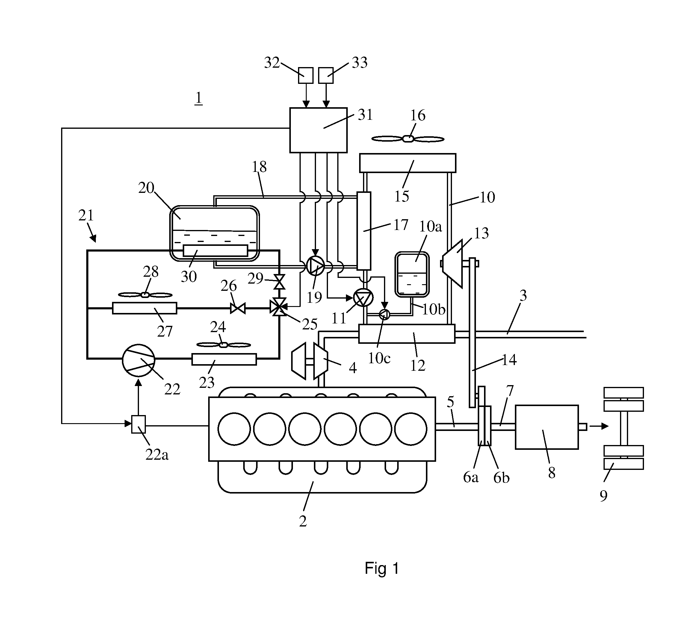
[0016]FIG. 1 depicts an arrangement for conversion of thermal energy to mechanical energy in a schematically depicted vehicle 1 powered by a supercharged combustion engine 2. The vehicle 1 may be a heavy vehicle powered by a supercharged diesel engine. The exhaust gases from the engine's cylinders are led to an exhaust line 3 which comprises a turbine 4 in a turbo unit. The vehicle has a power train starting with the combustion engine 2, a shaft 5, a flywheel 6a, a clutch 6b, a shaft 7, a gearbox 8 etc. The power train ends with a pair of powered wheels 9. The power train rotates as a unit when the clutch 6b is engaged.

[0017]The vehicle is equipped with an arrangement for recovery of thermal energy. The arrangement may be referred to as a WHR (waste heat recovery) system and comprises a line circuit 10 with a pump 11 adapted to circulating and pressurising a working medium in the line circuit. The working medium is led from the pump 11 to an evaporator 12 in which it is warmed by ex...


PUM


Abstract

An arrangement for converting thermal energy to mechanical energy in a vehicle (1). A working medium is vaporised by a heat source (3) in the vehicle (1) and is thereafter expanded through a turbine (13) generating mechanical energy. A control unit (31) receives information indicating the vehicle (1) is to be braked and connects the cooling system (21, 39) of the vehicle to the vehicle's power train (2, 5-9) to cool a refrigerant to a low temperature. The control unit (31) receives information that the vehicle (1) requires extra propulsive force and, uses the cooled refrigerant to subject the working medium in the line circuit (10) to a second step of cooling before it is led to the evaporator (12). The condensation temperature of the working medium may thus be lowered and more mechanical energy may be generated in the turbine (13).

Description

BACKGROUND TO THE INVENTION AND PRIOR ART[0001]The present invention relates to an arrangement for converting thermal energy to mechanical energy in a vehicle according to the preamble of claim 1.[0002]When fuel is burnt in a combustion engine, chemical energy is converted to mechanical energy. A substantial part of the chemical energy is not converted to mechanical energy but to thermal energy which is released to the surroundings in various ways. An example of this is the thermal energy in the exhaust gases which are discharged to surrounding air. A known practice is to use WHR (waste heat recovery) systems in vehicles to capture thermal energy and convert it to mechanical energy. A WHR system comprises a pump which circulates a working medium in a line circuit. The line circuit comprises an evaporator in which the working medium is warmed so that it is vaporised and extra-heated by means of a heat source which may with advantage be exhaust gases from a combustion engine, and a tu...

Claims


Application Information

Patent Timeline
Patent Type & Authority Applications(United States)
IPC IPC(8): F02B37/00
CPCF02B37/00B60T1/10B60W10/06B60W10/30B60W30/188B60W30/1882B60W30/1886B60L50/16F01K23/065F01K23/101F01P3/20Y02T10/12Y02T10/7072B60K6/12F01N5/02F01P7/00F02G5/02F25B27/02B60W30/18127F01P2060/06Y02T10/70
Inventor KARDOS, ZOLTANHALL, OLA
Owner SCANIA CV AB
Why Eureka
Try Eureka