Heat exchanger, in particular of the condensation type

a technology of heat exchanger and condensation type, which is applied in the direction of indirect heat exchanger, air heater, light and heating apparatus, etc., can solve the problems of coiled pipes, increased complexity of heat exchanger construction, and long construction tim

Active Publication Date: 2007-01-04
COSMOGAS
View PDF18 Cites 19 Cited by
  • Summary
  • Abstract
  • Description
  • Claims
  • Application Information

AI Technical Summary

Benefits of technology

[0006] In the light of the foregoing considerations, the purpose of the present invention is to provide a new-concept heat exchanger, which presents efficiency of operation, compact dimensions and is industrially simple and economically advantageous to produce.

Problems solved by technology

In order to have available a high surface of heat exchange the coiled pipe must, however, be rather long, and this at the expense of the requirement of rendering the dimensions of the heat exchanger as a whole compact.
If on the one hand said solution enables a good heat exchange to be obtained even with a coil that is not too long, on the other hand it involves a greater complexity of construction of the heat exchanger, with a consequent increase in its cost.
Another drawback of known heat exchangers is that they must be adequately insulated thermally, for example to prevent excessive heating of the body of the boiler.
The need to reduce the temperature of the casing of the heat exchanger in this way involves the use of insulators, which further complicate the construction of the heat exchanger, as well as its disposal at the end of its useful working life.

Method used


Image

  • Heat exchanger, in particular of the condensation type
  • Heat exchanger, in particular of the condensation type
  • Heat exchanger, in particular of the condensation type

Examples


Embodiment Construction

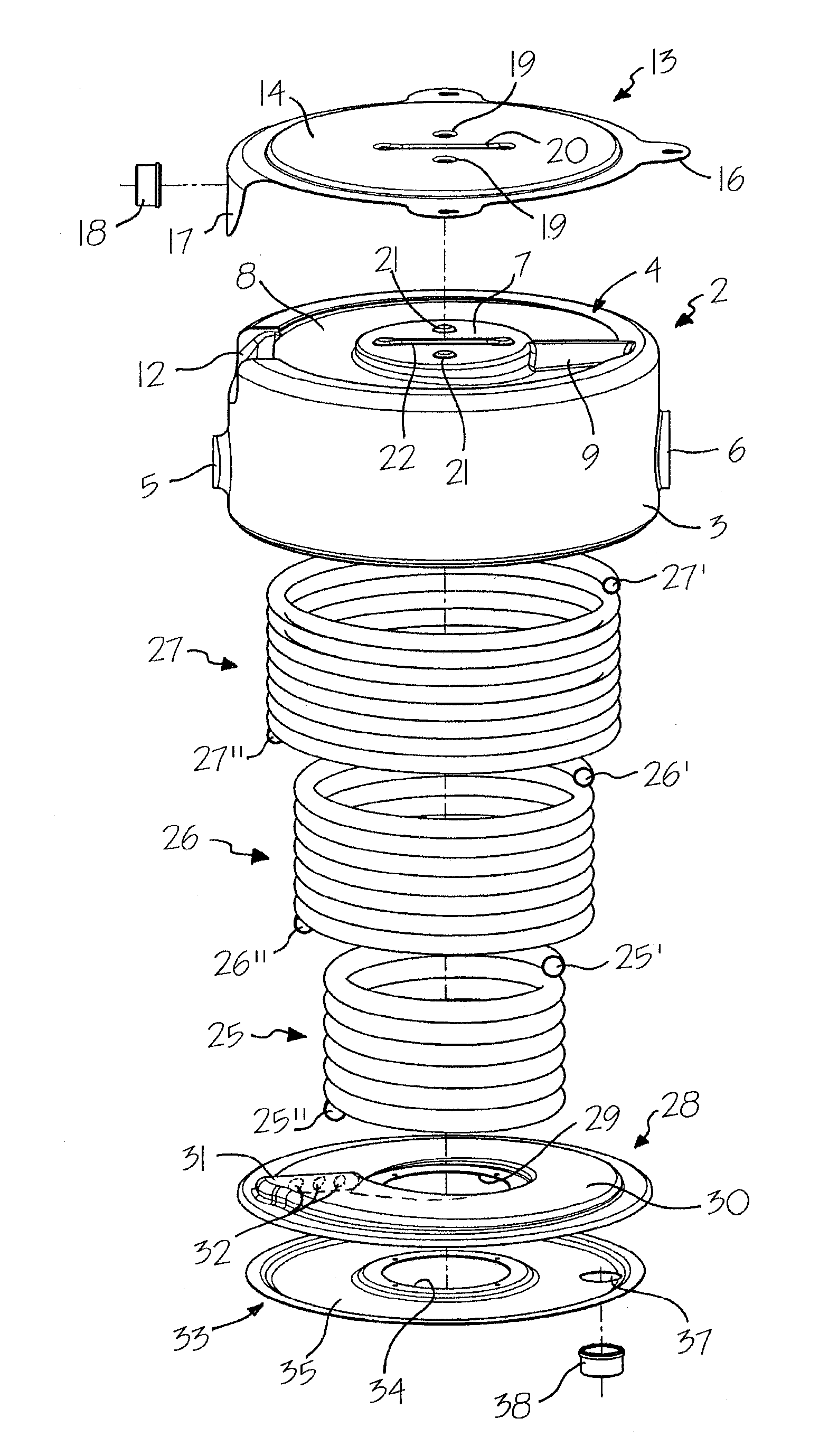
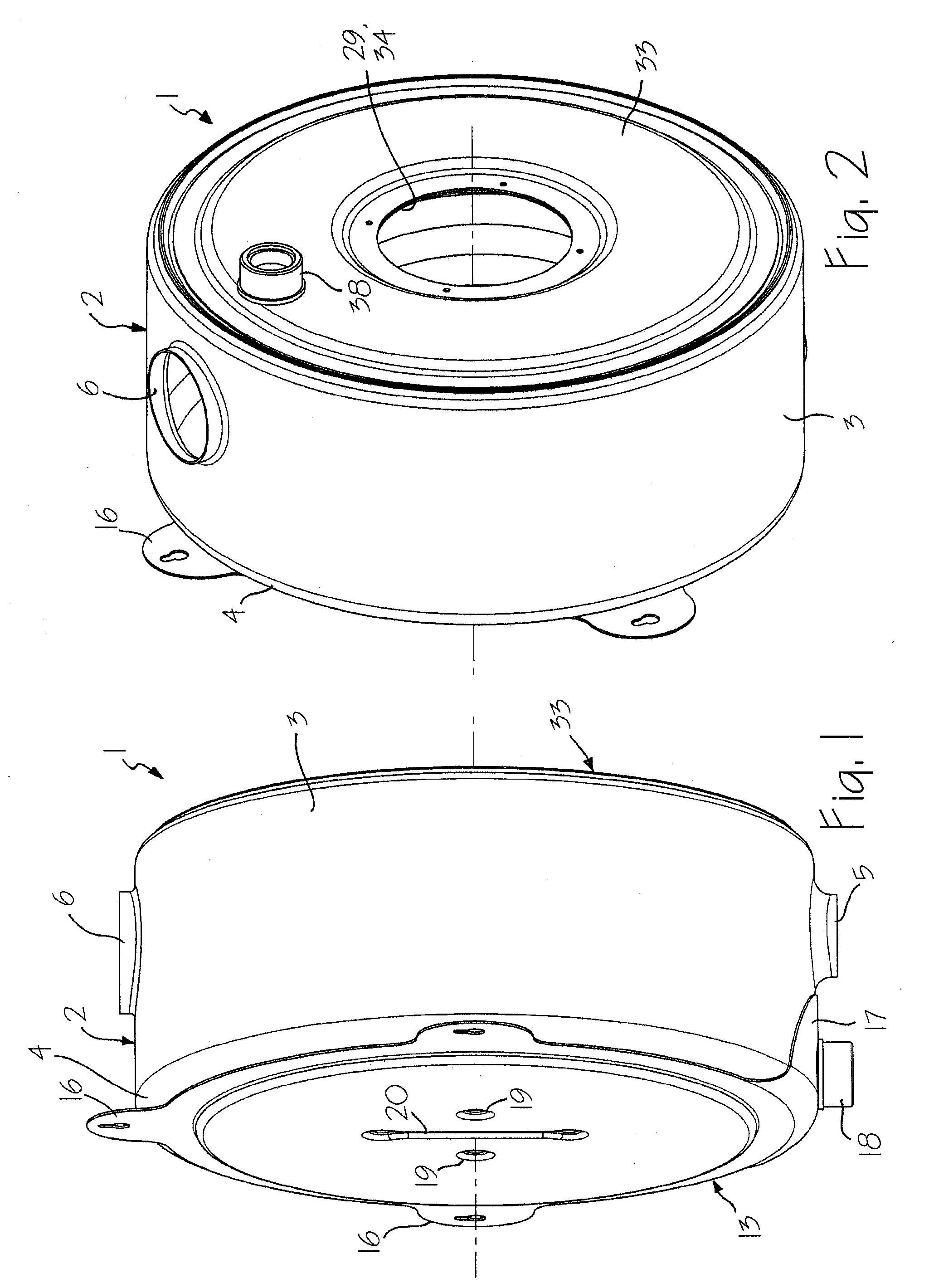
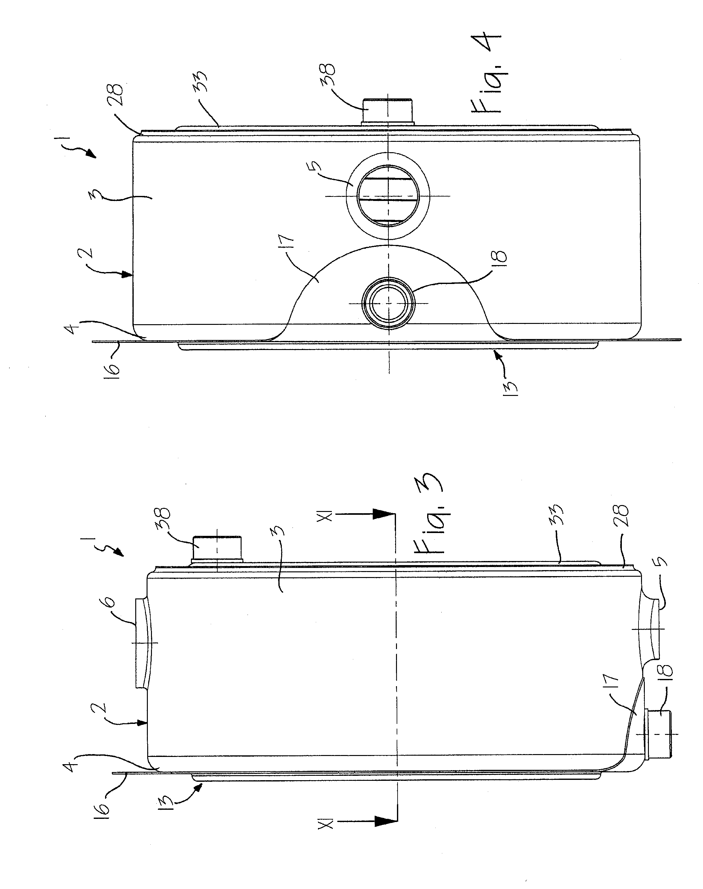
[0020] In the figures, reference number 1 indicates as a whole a heat exchanger, in particular of the condensation type for a gas boiler, built according to the present invention.

[0021] The heat exchanger 1 comprises a bell-like casing 2 made of thermally conductive material, preferably stainless steel, obtained by deformation of sheet metal, via operations of shearing, drawing, and pressing.

[0022] The casing 2 has a substantially cylindrical circumferential wall 3 and an end wall 4. In diametrally opposite areas of the wall 3 there are formed, once again by operations of drawing and shearing, a condensate-outlet connector 5 and a fume-outlet connector 6, which extend radially with respect to the axis of the casing 2.

[0023] As may be seen, in particular in FIGS. 6 and 7, the end wall 4 has a central area 7, around which there is formed, via drawing, an annular depression 8, facing the outside of the casing 2 and having a depth that is progressively variable in a circumferential d...


PUM


Abstract

A heat exchanger (1) comprises a casing (2, 13, 28, 33), within which there is present a first pipe wound in a spiral (25), in which a first fluid flows, the casing (2) being designed to receive a second fluid that is in heat-exchange relationship with the first fluid. The heat exchanger further comprises at least one second pipe wound in a spiral (26, 27), which connects, in parallel to the first pipe (25), two gaps (15, 36) formed in the casing (2, 13, 28, 33), the spiralled pipes (25, 26, 27) being arranged in a coaxial way and at a distance from one another, and having different sections of passage.

Description

FIELD OF THE INVENTION [0001] The present invention relates to a heat exchanger, in particular of the condensation type. BACKGROUND OF THE INVENTION [0002] As is known, the function of a heat exchanger is to transfer thermal energy between two fluids. For example, in the case of the widely used domestic gas boilers, the function of the heat exchanger is to heat water circulating inside it, starting from hot fumes that result from combustion produced by a burner. Said condensation boilers are devised for said purpose in order to exploit both heat that develops following upon combustion and latent heat of condensation contained in the combustion fumes. Heat contained in the fumes can be recovered via a heat exchanger comprising a shell or casing, inside which is set a pipe for circulation of water, against which the fumes are made to flow. [0003] The amount of condensation that is recovered mainly depends upon the temperature of delivery and return of the water in the heat exchanger, ...

Claims


Application Information

Patent Timeline
Patent Type & Authority Applications(United States)
IPC IPC(8): F28D7/02F24H1/43F24H8/00F28F13/08
CPCF24H1/43F24H8/00Y02B30/102F28F13/08F28D7/024Y02B30/00
Inventor ALESSANDRINI, ALBERTOALESSANDRINI, ANDREA
Owner COSMOGAS
Why Eureka
Try Eureka