Liquid crystal display unit and driving method therefor and drive device for liquid crystal display panel

a technology of liquid crystal display and driving method, which is applied in the direction of static indicating device, non-linear optics, instruments, etc., can solve the problems of residual dc voltage increasing flickering, display voltage vp actually applied to the pixel electrode is not completely symmetrical, and display cannot be appropriately realized, so as to prevent flickering and reduce power consumption

Inactive Publication Date: 2007-01-04
SANYO ELECTRIC CO LTD
View PDF14 Cites 36 Cited by
  • Summary
  • Abstract
  • Description
  • Claims
  • Application Information

AI Technical Summary

Benefits of technology

[0031] According to the present invention, power consumption can be reduced while preventing occurrence of flickering in an LCD.

Problems solved by technology

However, LCDs often do not employ a method in which a horizontal scan line of an odd number and a horizontal scan line of an even number are driven at the odd field and even field, respectively, in one frame period (interlace drive) similar to a well-known display method of CRT display devices; rather, LCDs often employ a method in which all pixels (horizontal scan lines of odd and even numbers) are sequentially driven a plurality of times (for example, two times) (non-interlace drive) in one frame period.
However, as shown in FIG. 12 (a), the waveform of the display voltage Vp actually applied to the pixel electrode is not completely symmetrical in the positive polarity field period and the negative polarity field period.
In addition, in conventional LCDs, when a display voltage Vp having the same polarity is applied for two field periods or longer, the residual DC (direct current voltage) component applied to the liquid crystal layer becomes significantly large and, even when a display voltage Vp corresponding to the display content to be applied to the liquid crystal is applied to the pixel electrode, the voltage applied to the liquid crystal is changed by the residual DC voltage, resulting in problems that display cannot be appropriately realized and that the residual DC voltage increases flickering.

Method used


Image

  • Liquid crystal display unit and driving method therefor and drive device for liquid crystal display panel
  • Liquid crystal display unit and driving method therefor and drive device for liquid crystal display panel
  • Liquid crystal display unit and driving method therefor and drive device for liquid crystal display panel

Examples


Embodiment Construction

[0046] Preferred embodiments (hereinafter simply referred to as “embodiments”) of the present invention will now be described by reference to the drawings.

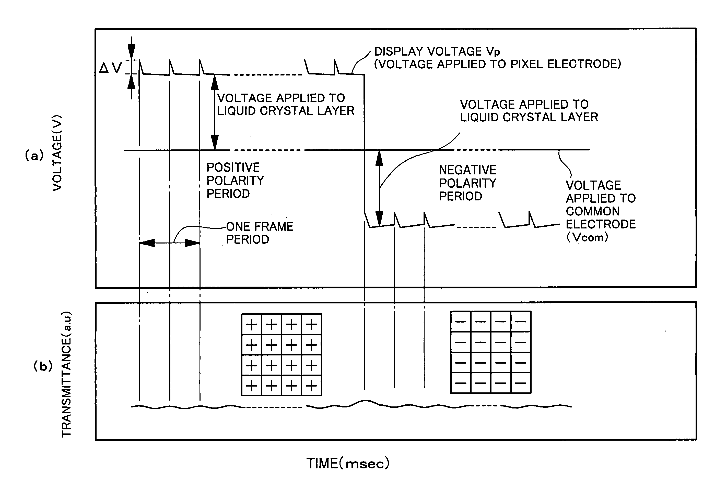
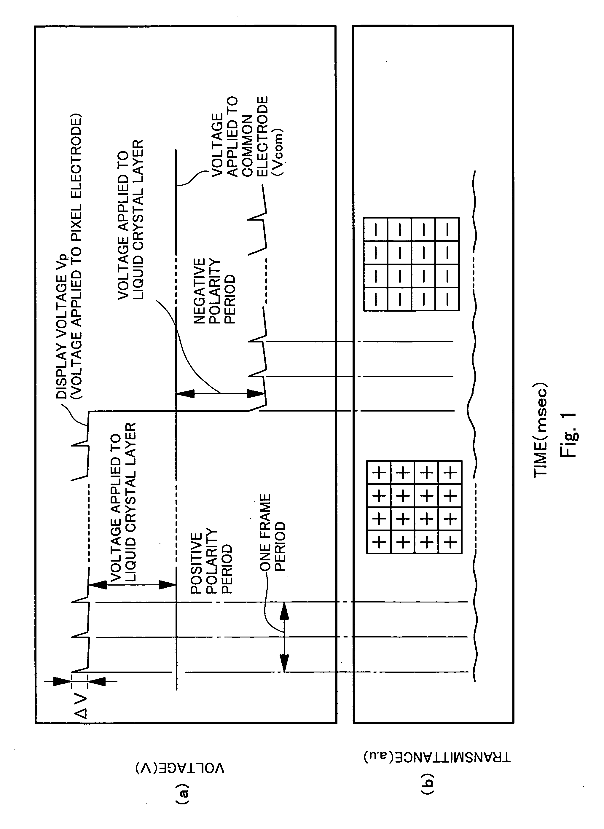
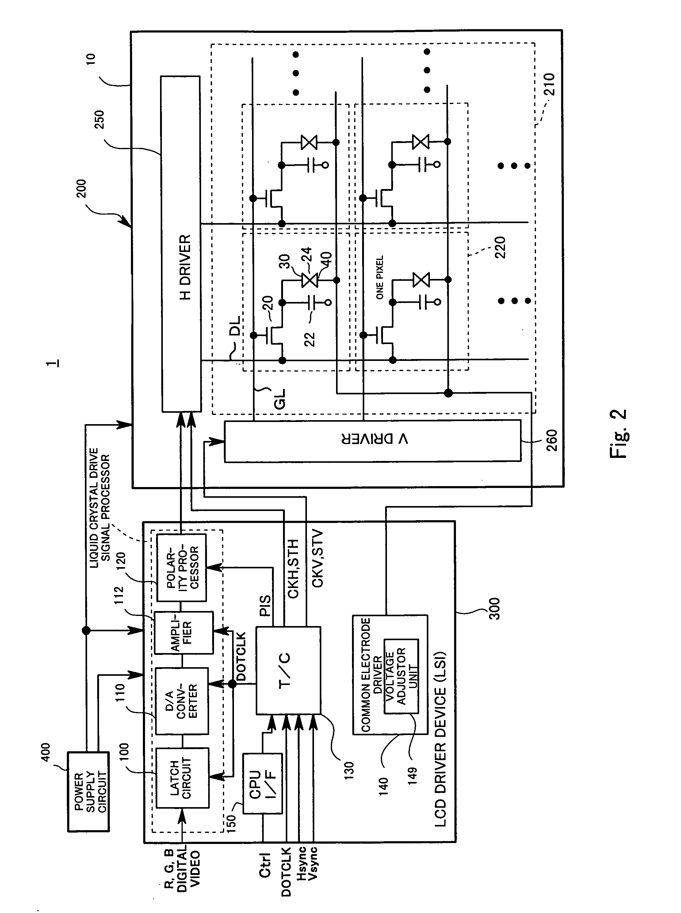
[0047] In an LCD according to the present embodiment, an inversion period of polarity of a liquid crystal drive voltage with respect to a reference value is set to a period of two frame periods or longer. In the LCD of the present embodiment, all pixels forming one screen are set at the same polarity and the polarity is inverted for each screen, and line inversion and dot inversion, in which the polarities of pixels on one screen differ for each line or each pixel, are not executed. In addition, the polarity inversion drive is not limited to an active matrix LCD having a switch such as a TFT in each pixel and may be applied to a passive matrix LCD or the like having no switch. However, in the following description, the present embodiment will be described by reference to an active matrix LCD intrinsically having a high display qu...


PUM

PropertyMeasurementUnit
drive frequencyaaaaaaaaaa
frequencyaaaaaaaaaa
frequencyaaaaaaaaaa

Abstract

The polarity inversion cycle of a voltage applied to a liquid crystal layer is set to at least 2-frame cycle, or more preferably to as long as about 10 sec. Accordingly, a flicker that could not have been prevented at a polarity inversion cycle of about one frame can be prevented, and a longer inversion cycle can reduce power consumption. A material low in ion reactivity and small in residual polarization is used as a liquid crystal material or an orientation film material, thereby preventing the occurrence of a residual DC component in a liquid crystal layer and the deterioration of display quality despite a longer polarity inversion cycle. In the case of an LCD provided with a minimal transmittance with respect to an applied voltage, black can be accurately displayed by, for example, regulating a common electrode potential so that an applied voltage at which the transmittance of a liquid crystal shows a minimum value during an anodic application period is equal to that during a cathodic application period.

Description

TECHNICAL FIELD [0001] The present invention relates to a liquid crystal display device, and, more particularly, to polarity inversion of a voltage to be applied to a liquid crystal layer. BACKGROUND ART [0002] Liquid crystal display devices exhibiting small thickness and size and low power consumption are currently employed as display devices in various devices. A liquid crystal display device (hereinafter referred to as “LCD”) has a structure in which liquid crystal is sealed between two substrates, and electrodes are formed on the respective substrates so as to oppose each other. In the LCD, display is achieved by applying a voltage signal between the electrodes in order to control alignment of the liquid crystal in which optical characteristics change depending on the alignment state, to thereby control transmittance of light from a light source. [0003] As is conventionally known, when a direct current voltage is continuously applied between the electrodes formed on opposing sur...

Claims


Application Information

Patent Timeline
Patent Type & Authority Applications(United States)
IPC IPC(8): G09G3/36G02F1/1337G02F1/1343
CPCG02F1/1337G02F2001/134381G09G3/3655G09G3/3648G09G3/3614G02F1/134381G02F1/133
Inventor KOMA, NORIO
Owner SANYO ELECTRIC CO LTD
Why Eureka
Try Eureka