Display device and method of driving the same

a liquid crystal display device and display device technology, applied in the direction of static indicating devices, instruments, etc., can solve the problems of difficult interlace image signal display on progressive type liquid crystal display devices, heavy cathode ray tubes (crts) and heavy weight, and achieve the effect of preventing afterimages and flickers

Inactive Publication Date: 2007-01-04
LG DISPLAY CO LTD
View PDF11 Cites 19 Cited by
  • Summary
  • Abstract
  • Description
  • Claims
  • Application Information

AI Technical Summary

Benefits of technology

[0025] Another object of the present invention is to provide a liquid crystal display device and a method of driving the same that prevent afterimages and flickers.

Problems solved by technology

Cathode ray tubes (CRTs) are heavy and bulky.
Accordingly, it is difficult for a PDP device or an LCD device to display TV signals as-is.
On the other hand, when an interlace image signal supplied from a broadcasting station is supplied to a liquid crystal display device, it is difficult to display the interlace image signal on the progressive type liquid crystal display device.
However, additional devices, e.g., a data converter and a frame memory, are required to convert the interlace image signal into the progressive image signal before applying to a liquid crystal display device, such that a circuit of the liquid crystal display device becomes complicated and manufacturing cost is increased.
Therefore, the DC voltage having the positive polarity remains in the pixel, thereby generating severe afterimages.
However, even when the afterimage is prevented by inverting the polarity of the pixel data by the two-field period, flickers are generated.
Therefore, since an actual image is not displayed during the EF period due to the influence of the remaining DC voltage in the OF period, flickers are generated.

Method used


Image

  • Display device and method of driving the same
  • Display device and method of driving the same
  • Display device and method of driving the same

Examples


Embodiment Construction

[0047] Reference will now be made in detail to preferred embodiments of the present invention, examples of which are illustrated in the accompanying drawings.

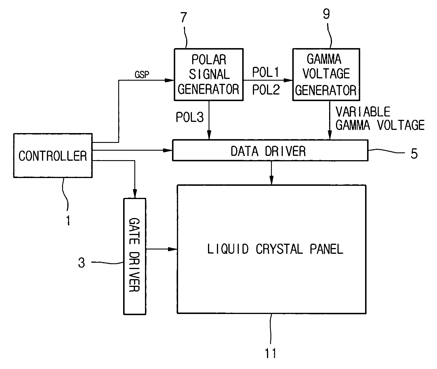
[0048]FIG. 7 is a block diagram illustrating a liquid crystal display device according to an embodiment of the present invention. In FIG. 7, a liquid crystal display device includes a controller 1, a gate driver 3, a data driver 5, a polar signal generator 7, a gamma voltage generator 9, and a liquid crystal panel 11.

[0049] The controller 1 receives interlace image signals including odd-fields and even-fields from an external graphic card (not shown). In particular, for odd-fields, the controller 1 generates dummy pixel data on even horizontal lines using actual pixel data on adjacent odd horizontal lines of the odd-fields to form one frame, and for even-fields, the controller 1 generates dummy pixel data on odd horizontal lines using actual pixel data on adjacent even horizontal lines of the even-fields to form one frame.

[0...


PUM


Abstract

A driving circuit of a liquid crystal display device capable of processing interlace type video signals, includes a data driver inverting a polarity of a pixel data at least every two-field period, converting the pixel data every field period according to a variable gamma voltage, and supplying the inverted pixel data to a liquid crystal display panel, a value of the gamma voltage changing every field period.

Description

[0001] The present invention claims the benefit of Korean Patent Application No. 057546 / 2005 filed in Korea on Jun. 30, 2005, which is hereby incorporated by references. BACKGROUND OF THE INVENTION [0002] 1. Field of the Invention [0003] The present invention relates to a display device, and more particularly, to a liquid crystal display device and a method of driving the same that provide improved image quality. [0004] 2. Discussion of the Related Art [0005] Cathode ray tubes (CRTs) are heavy and bulky. To solve these disadvantages of the CRTs, flat panel display devices have been developed. Examples of the flat panel display devices include a liquid crystal display device (LCD), a field emission display (FED), a plasma display panel (PDP), and an electro-luminescence (EL) display device. The flat panel display device displays an image on a panel using an external image signal, e.g. a computer display signal or a television broadcast signal. The flat panel display device for displa...

Claims


Application Information

Patent Timeline
Patent Type & Authority Applications(United States)
IPC IPC(8): G09G3/36
CPCG09G3/3614G09G3/3688G09G2320/0276G09G2320/0247G09G2320/0257G09G2310/0229
Inventor LEE, JU YOUNGCHUN, JAE BUM
Owner LG DISPLAY CO LTD
Why Eureka
Try Eureka