Method and system for establishing an emergency call in a communications system

Inactive Publication Date: 2007-01-04
CORE WIRELESS LICENSING R L
View PDF12 Cites 56 Cited by
  • Summary
  • Abstract
  • Description
  • Claims
  • Application Information

AI Technical Summary

Benefits of technology

[0018] It is an aim of embodiments of the present invention to ad

Problems solved by technology

However, this solution is not optimised in situations in which there are two or more PSAP service areas that over lap with t

Method used


Image

  • Method and system for establishing an emergency call in a communications system
  • Method and system for establishing an emergency call in a communications system
  • Method and system for establishing an emergency call in a communications system

Examples


Embodiment Construction

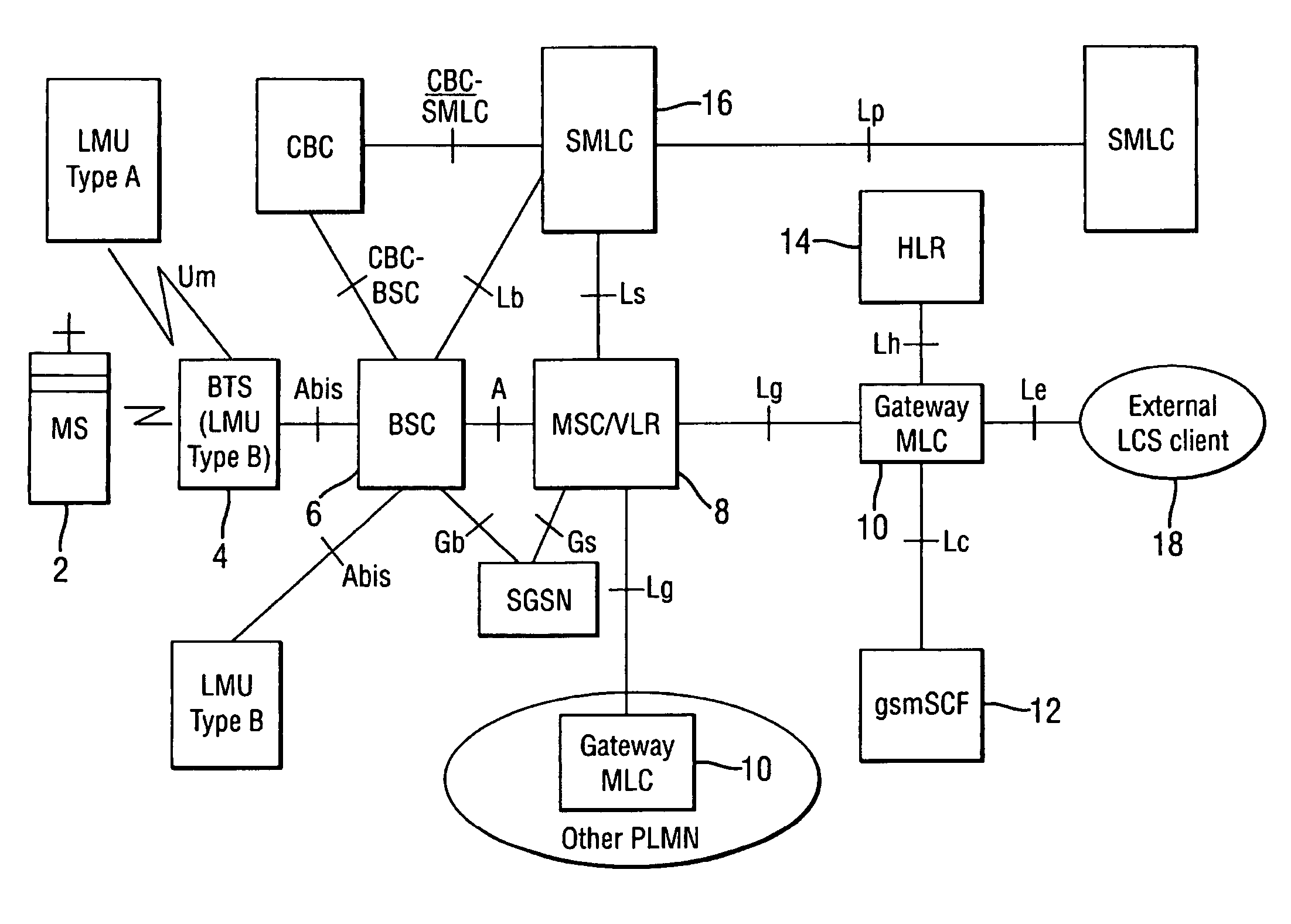
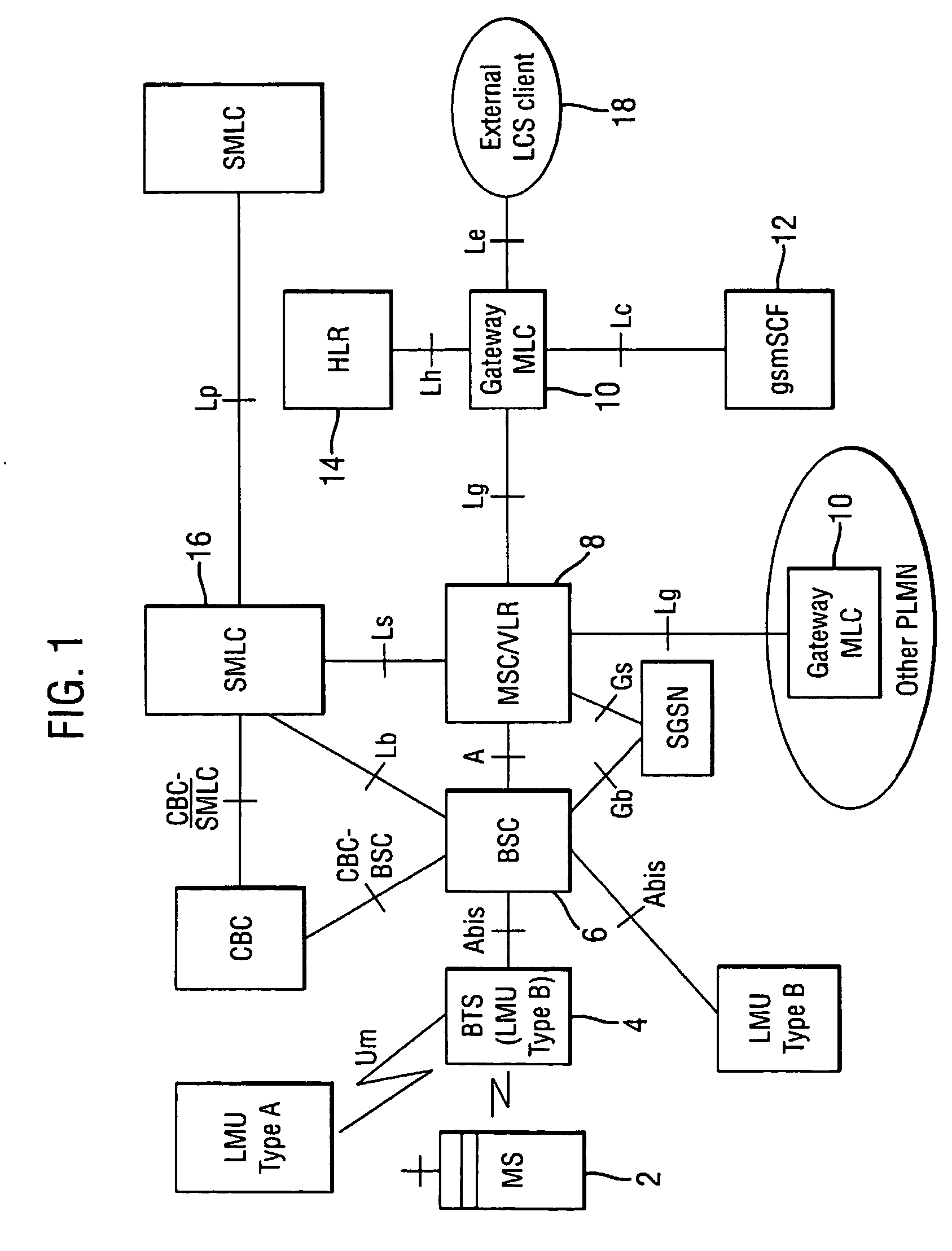
[0042]FIG. 1 shows the generic LCS (Location Services) logical architecture as specified in the 3GPP TS 03.71 Release 99 specification for the Functional Descriptions of Location Services.

[0043] An MS 2 is shown connected to a BTS 4 having a particular cell coverage dependant on the transmission power of the BTS 4. The BTS 4 can have the LMU functionality in the BTS itself or separate. The BTS 4 is connected to a BSC 6 (Base Station Controller), which typically controls a plurality of BTSs each having their own cell coverage. The BSC 6 can be connected to an SMLC 16 (Serving Mobile Location Centre) or to an MSC 8. The MSC 8 typically controls a plurality of BSCs and has a VLR (Visitor Location Register), which maintains a database of the details of the MS when entering into a visited network.

[0044] The SMLC resides either at the core network level or the radio level and has the functionality for receiving locations measurement signals from the MS 2, and the SMLC is able to compute...


PUM


Abstract

A method for establishing an emergency call between a user equipment within a radio coverage area and one of at least two points able to answer the call, the method comprising: receiving said emergency call request; determining a first estimate of the position of said user equipment within said coverage area; interrupting said call establishment by triggering a control point; and using the control point to select, based on said first position estimate, which one of said at least two answering points the call is established with.

Description

FIELD OF THE INVENTION [0001] The present invention relates to a method and system for locating user equipment within a communications network. BACKGROUND OF THE INVENTION [0002] A cellular telecommunications system is a communication system that is based on use of radio access entities and / or wireless service areas. The access entities operate over respective coverage areas that are typically referred to as cells. Examples of cellular telecommunications systems include standards such as the GSM (Global System for Mobile communications) or various GSM based systems (such as GPRS: General Packet Radio Service), AMPS (American Mobile Phone System), DAMPS (Digital AMPS), WCDMA (Wideband Code Division Multiple Access), TDMA / CDMA (Time Division Multiple Access / Code Division Multiple Access) in UMTS (Universal Mobile Telecommunications System), CDMA 2000, i-Phone and so on. [0003] In a cellular system, a base transceiver station (BTS) provides a wireless communication facility that serves...

Claims


Application Information

Patent Timeline
IPC IPC(8): H04M11/04H04W4/90
CPCH04W4/22G01S5/02H04W76/007H04W76/50H04W4/90G01S5/0244
Inventor MUHONEN, JANNE MARKUS
Owner CORE WIRELESS LICENSING R L
Why Eureka
Try Eureka