Eureka AIR delivers breakthrough ideas for toughest innovation challenges, trusted by R&D personnel around the world.

Selective transmission of mobile radio communications system service information

a mobile radio communication system and service information technology, applied in the field of radio communication systems, can solve the problems of consuming precious radio transmission resources, consuming base station transmission power, creating interference, etc., and reducing unnecessary interference in other parts of the cell, reducing the effect of transmission resources

Inactive Publication Date: 2006-10-19
TELEFON AB LM ERICSSON (PUBL)
View PDF6 Cites 30 Cited by
  • Summary
  • Abstract
  • Description
  • Claims
  • Application Information

AI Technical Summary

Benefits of technology

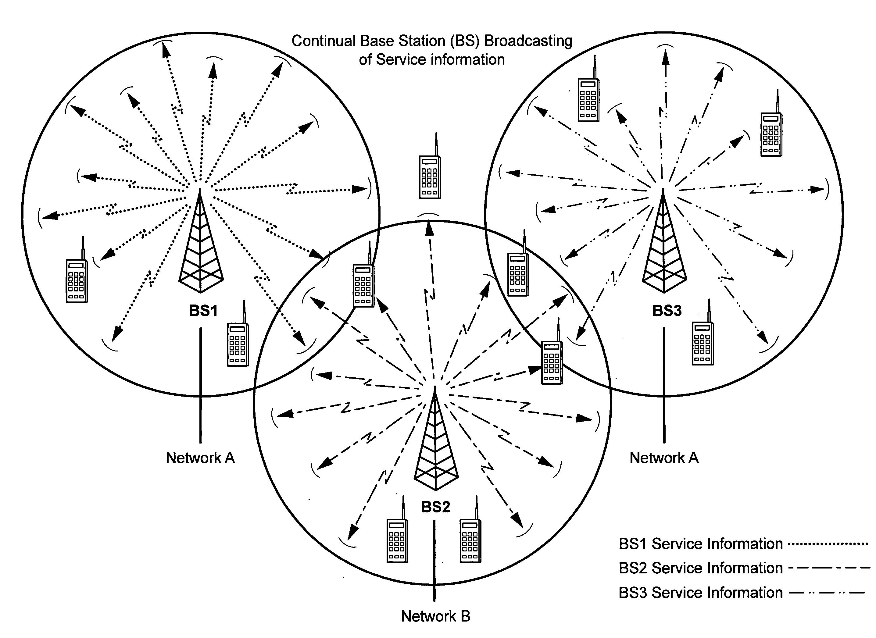
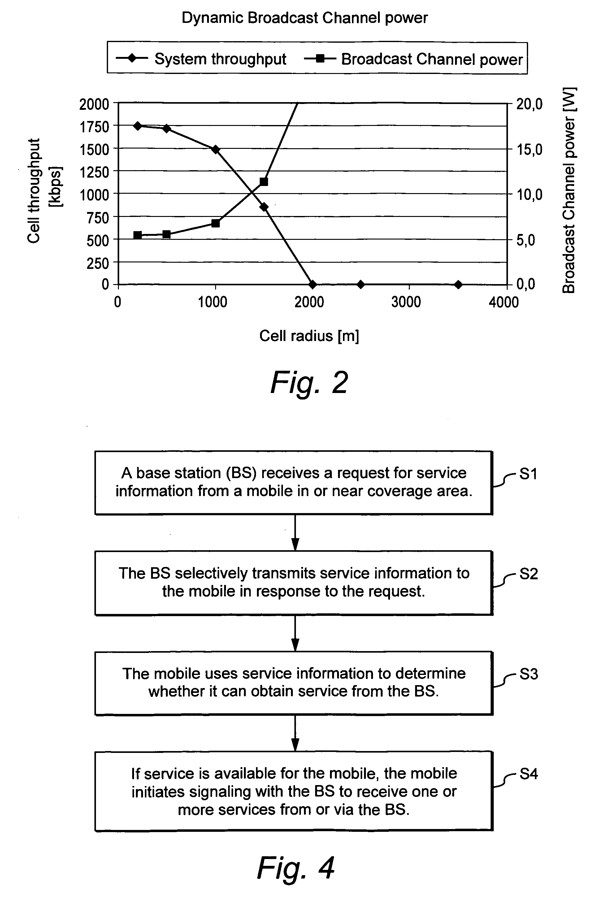
The patent text describes a method for selectively transmitting service information to mobile radios based on their requests, rather than constantly broadcasting the information. This approach frees up resources and reduces interference. The service information can include information about the operator, the mobile radios allowed to use the service, and the access principle. The mobile radios can also request additional information using a pilot signal. The base station can use directional antenna beams to further decrease interference and improve cell coverage. Overall, this method allows for more efficient use of resources and better service for mobile radios.

Problems solved by technology

Broadcasting service information (usually with an associated pilot signal) consumes precious radio transmission resources.
In particular, it consumes base station transmission power and creates interference (interference being a resource in the sense that a cell can only function satisfactorily when the interference is below a certain level).
Because the service information has to be received in the whole coverage area, even greater transmission power will likely be necessary in sparsely deployed systems.

Method used


Image

  • Selective transmission of mobile radio communications system service information
  • Selective transmission of mobile radio communications system service information
  • Selective transmission of mobile radio communications system service information

Examples


Embodiment Construction

[0023] In the following description, for purposes of explanation and non-limitation, specific details are set forth, such as particular nodes, functional entities, techniques, protocols, standards, etc. in order to provide an understanding of the described technology. It will apparent to one skilled in the art that other embodiments may be practiced apart from the specific details disclosed below. In other instances, detailed descriptions of well-known methods, devices, techniques, etc. are omitted so as not to obscure the description with unnecessary detail. Individual function blocks are shown in the figures. Those skilled in the art will appreciate that the functions of those blocks may be implemented using individual hardware circuits, using software programs and data in conjunction with a suitably programmed microprocessor or general purpose computer, using applications specific integrated circuitry (ASIC), and / or using one or more digital signal processors (DSPs).

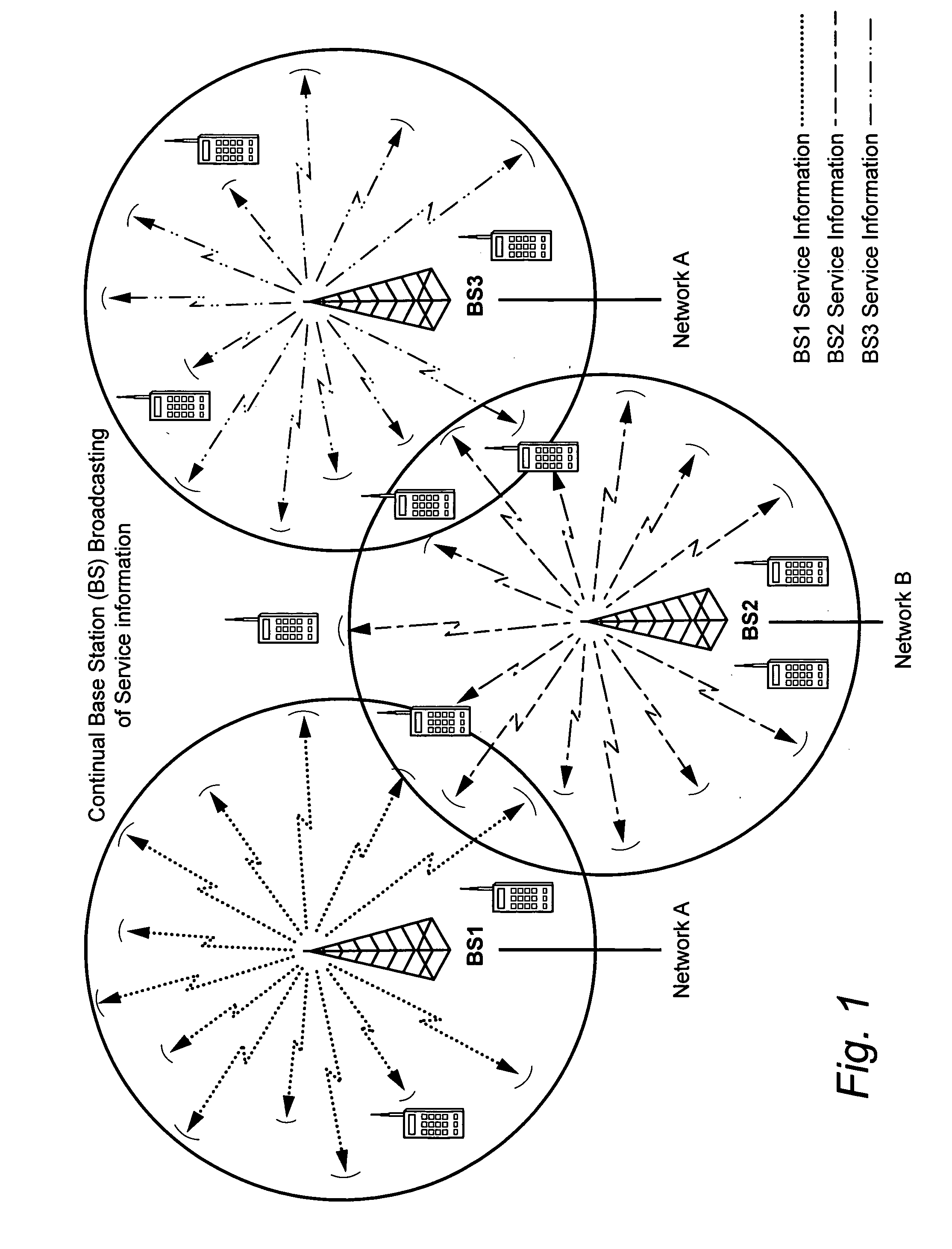
[0024]FIG. 1...


PUM


Abstract

A radio base station does not broadcast service information without a request from a mobile radio terminal. When a mobile radio enters or approaches a coverage area of the base station, it transmits a service information request in or near the radio coverage area. The service information is associated with the radio coverage area. When the base station receives the request for service information from the mobile radio, the base station then selectively transmits the service information to the mobile radio, either immediately or after some exchange between the mobile radio and the base station. The service information allows the mobile radio to determine whether the mobile terminal is permitted to obtain service from the radio base station. The base station does not usually broadcast service information in the radio coverage area independently of a request from a mobile radio thereby conserving resources and reducing interference.

Description

TECHNICAL FIELD [0001] The technical field relates to radio communications systems, and more particularly, to providing system service information to mobile radio terminals from radio base stations. BACKGROUND AND SUMMARY [0002] Cellular radio communication systems require that mobile radio stations acquire detailed information about the system before attempting access. “System information” typically identifies the system or network operator and allows the mobile radio to determine if it is allowed to access the network for service. The system information may also include information necessary for the mobile radio to successfully interact with the system, such as channel layout in the frequency, time, or code domain, communications protocol details, etc. System information is typically broadcasted by each radio base station over the geographical coverage area serviced by that base station. By continually transmitting the system information, any mobile station in the coverage area ca...

Claims


Application Information

Patent Timeline
Patent Type & Authority Applications(United States)
IPC IPC(8): H04Q7/20H04W48/14H04W48/20
CPCH04W48/20H04W48/14
Inventor WIBERG, NICLASPERSSON, MAGNUS S.
Owner TELEFON AB LM ERICSSON (PUBL)
Why Eureka
Eureka Blog
Learn More