Extendable soft stent with excellent follow-up capability to blood vessel

a soft stent and excellent follow-up technology, applied in the field of stents, can solve the problems of obstructing or stenosis of the lumen, difficult to insert the stent into the objective site, and the stents have sufficient flexibility, and achieve excellent trackability to the lumen, easy to form a lateral hole, and flexibility to bend

Active Publication Date: 2007-01-04
NIPRO CORP
View PDF6 Cites 3 Cited by
  • Summary
  • Abstract
  • Description
  • Claims
  • Application Information

AI Technical Summary

Benefits of technology

[0020] According to the present invention, it is possible to expect the following effects: (1) the whole stent is excellent in trackability to lumens since the stent as a whole possesses flexibility to bending because of the fact that the annular members forming the tubular wall of the stent are composed of repeated wavelike patterns, and it is easy to form a lateral hole; (2) the adjoining two annular members are connected by the connecting elements at the arched segment that connects the second linear segment and the third linear segment with small wave amplitudes of the wave pattern, there is substantially no change in length of the stent when expanding the stent, provided that the ratio between the distance from a radially halving line of the annular member to the top of the arched segment that connects the second linear segment and the third linear segment of the first annular member element, and the distance from a radially halving line of the annular member to the top of the arched segment that connects the first linear segment and the second linear segment of the second annular member element has been set to a value falling within the range of from 1:2 to 7:8. (3) since the adjoining two annular members are connected by the connecting members at the tops of the arched segments that are the mountains of the wavelike pattern, the tops of the arched segments are free from curvature deformation at the time of expansion of the stent and are reduced in curvature deformation at the time of bending of the stent, thus making it possible to minimize the damage of the lumens at the time of introduction of the stent into the objective site.

Problems solved by technology

These stents of the prior art have been improved to some extent, but they still put a load on the lumen such as the blood vessel in the vicinity of edges of the expanded stent, resulting in obstruction or stenosis of the lumen.
Further, it can not be said that these stents have sufficient flexibility, and thus it is often difficult to insert the stent into the objective site if the lumen has a three-dimensionally meandering course.
In addition, the stents may cause wounds in the blood vessel during insertion into the objective site.
If there is a branched blood vessel at the inflated position, it is hardily difficult to form a lateral hole in the placed stent.
Further, the stents have such a problem that the length of the stent is shortened by expansion, i.e., so-called shortening.

Method used


Image

  • Extendable soft stent with excellent follow-up capability to blood vessel
  • Extendable soft stent with excellent follow-up capability to blood vessel
  • Extendable soft stent with excellent follow-up capability to blood vessel

Examples


embodiment 1

Across the Bottom

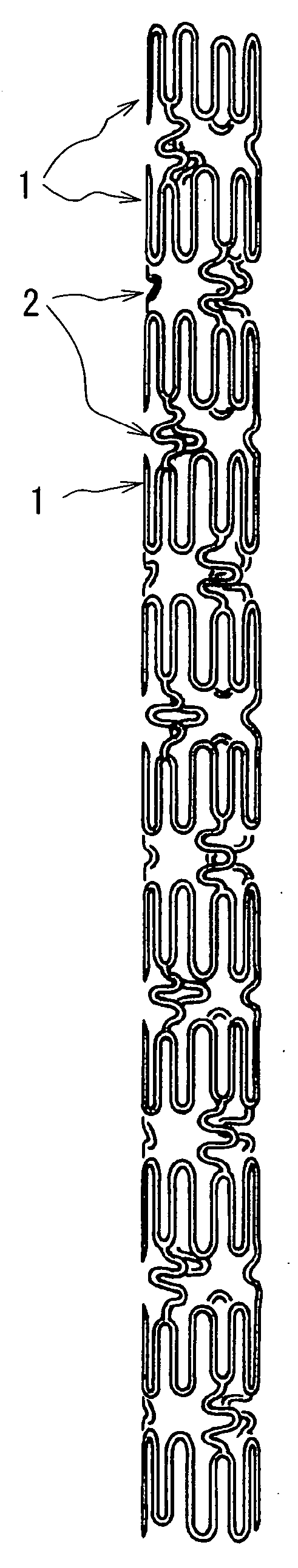
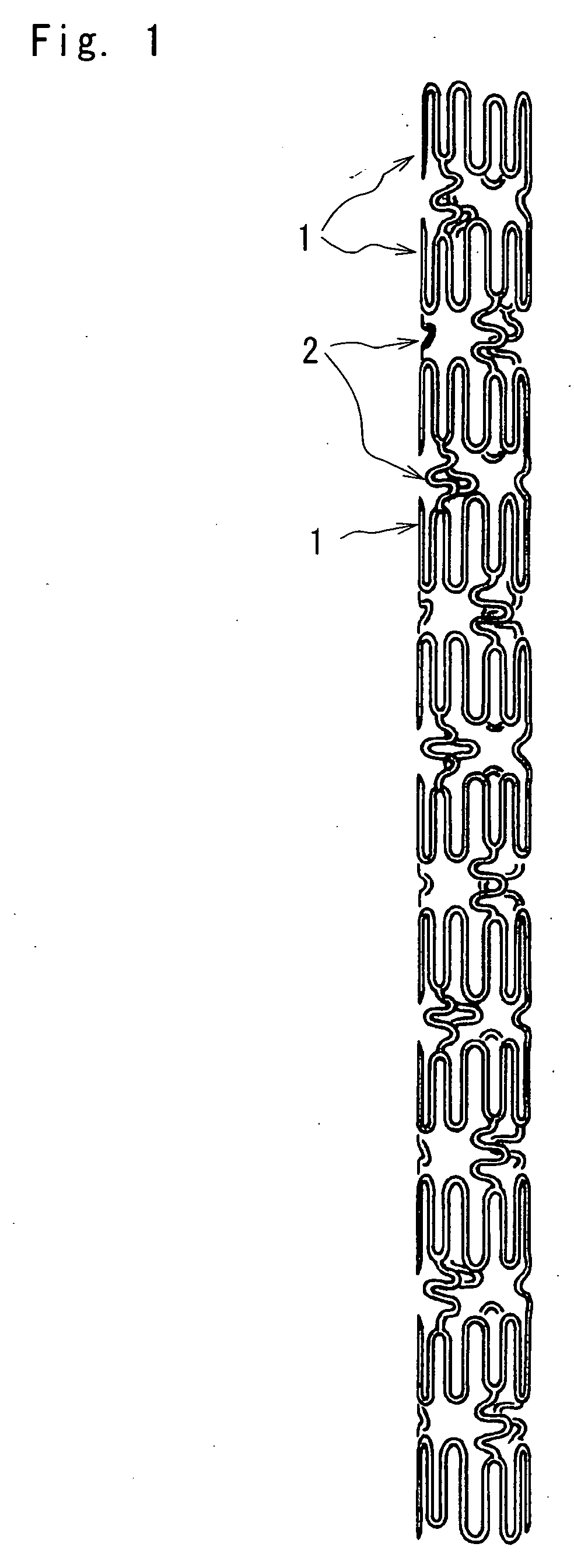
[0043]FIG. 1 is an enlarged plan view of a stent according to one embodiment of the present invention, FIG. 2 is a development of the stent shown in FIG. 1, FIG. 3 is an enlarged plan view illustrating an expanded state of the stent shown in FIG. 1, and FIG. 4 is a partially enlarged view of FIG. 2.

[0044] As shown in FIGS. 1 to 3, the stent of embodiment 1 is a tubular member comprising eleven annular members 1 arranged in the longitudinal direction of the stent for keeping a body lumen open, and connecting elements 2 arranged by threes between the longitudinally adjoining two annular members 1, 1 to connect them with one another. Each annular member 1 comprises three pieces of first annular member elements 11 and three pieces of second annular member elements 12, which are alternately interconnected in the circumferential direction to define the annular member, which is expandable in the radial direction.

[0045] The first annular member elements 11 and second annu...

embodiment 2

[0050] Embodiment 2 of the present invention will be demonstrated below, making reference to FIG. 6.

[0051] The stent of embodiment 2 is a modification of the stent of embodiment 1, wherein the ratio of distances from the radially halving line to the respective tops of the arched segments is set to 7:8, and the arched segments 125, 114, 3 and arched segments 124, 4, 115 are respectively aligned with one another at the proximal end of the annular member 5 on the proximal side of the stent or at the distal end of the annular member 6 on the distal side of the stent, and the connecting elements 2 are formed into a shape shown in FIG. 5E. As illustrated in FIG. 6, the stent comprises six annular members 1a-1f, which are radially expandable, and the adjoining two annular members 1 are connected to each other by three wavelike connecting elements 2 as shown in FIG. 5E.

[0052] The arched segments of the annular members situated at each end of the stent are respectively aligned along the pr...

embodiment 3

[0055] Embodiment 3 of the present invention will be demonstrated below, making reference to FIG. 7.

[0056] The stent of embodiment 3 is a modification of the stent of embodiment 1, in which the connecting elements 2 are formed into a shape as shown in FIG. 5D. As shown in FIG. 7, the stent comprises ten annular members 1 which are radially expandable and arranged in the direction of the longitudinal axis of the stent, the adjoining annular members 1, 1 are connected to each other by three wavelike connecting elements 2 shown in FIG. 5D. The aforementioned stent is excellent in trackability to lumens since the whole stent is flexible enough to respond to bending. Further, it is easy to provide the stent with a lateral hole. In addition, the tops of the arched elements are prevented from producing curvature deformation when expanding the stent and minimized in curvature deformation which may occur at the time of bending of the stent, thus making it possible to avoid any damage of the...


PUM


Abstract

The stent of the present invention is a tubular member comprising annular members 1 arranged in a longitudinal direction thereof for keeping a body lumen open, and one or more connecting elements 2 for connecting longitudinally adjoining two annular members 1, 1 with one another. Each annular member 1 comprises first annular member elements 11 and second annular member elements 12 which are alternately jointed together in the circumferential direction of the annular member 1. The annular members 1 are expandable in the radial direction thereof. The stent is flexible and excellent in trackability to lumens, thus making it possible to allow the stent to pass through the three-dimensionally meandering lumens. The stent is substantially free from shortening and makes it possible to provide the stent with a lateral hole.

Description

TECHNICAL FIELD [0001] The present invention relates to a stent that is implanted in a human body to maintain a diameter of a body lumen such as blood vessels. BACKGROUND ART [0002] So far, stents have been used to expand a diameter of the body lumen such as the blood vessel and keep it to the expanded luminal diameter. The stent may be expanded by various methods such as balloon dilation, self-expansion using a shape memory material, mechanical expansion, or the like. The most widely used method is the balloon dilation. In the balloon dilation, a stent is introduced into a desired site in the body together with a balloon catheter, expanded by inflation of balloon to dilate a diameter of the lumen, and retained at the dilated site even after removing the deflated balloon from the site. The stent generally comprises luminal diameter-holding portions for dilating and holding the diameter of the lumen such as blood vessel, and joint portions for connecting the luminal diameter-holding ...

Claims


Application Information

Patent Timeline
Patent Type & Authority Applications(United States)
IPC IPC(8): A61F2/06A61F2/89A61M29/02
CPCA61F2/91A61F2/915A61F2002/91558A61F2002/91516A61F2002/91533A61F2002/91508A61M29/02
Inventor SANO, YOSHIHIKOTANAKA, YUJI
Owner NIPRO CORP
Why Eureka
Try Eureka