
Helical screw lift system for an elevator

a technology of elevator car and helical screw, which is applied in the field of elevator car, can solve the problems of general obstructive construction, unsightly appearance, and the current lift system is not adaptable to being custom designed, and achieve the effect of preventing the inadvertent downward creep of the elevator car

Inactive Publication Date: 2007-01-11
NIELSEN KAJ GUY
View PDF8 Cites 21 Cited by
  • Summary
  • Abstract
  • Description
  • Claims
  • Application Information

AI Technical Summary

Benefits of technology

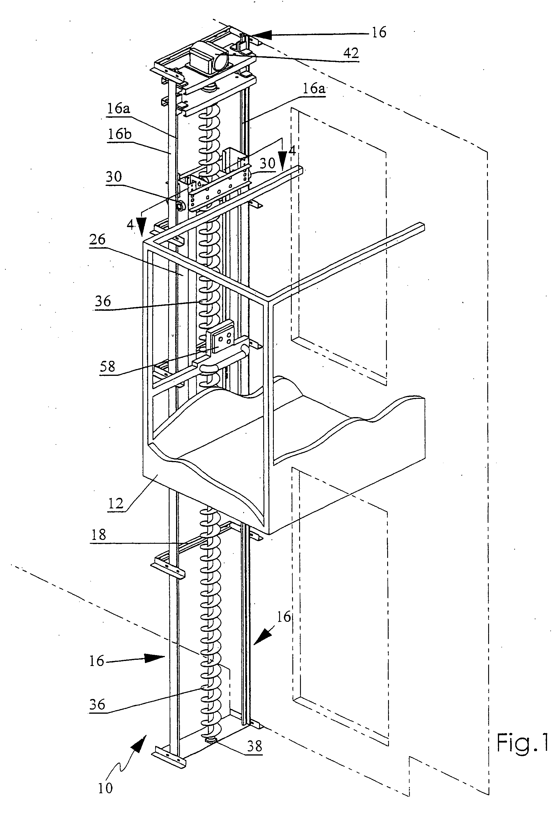
[0016] The helical screw is jounialled at its lower end on bearings mounted on a pedestal or base member. A reversible electric motor is mounted to the opposite upper end of the helical screw to selectively rotate the screw to either raise or lower the car supporting carriage frame. In one embodiment, a self locking speed reducer may be employed, mounted between the motor and screw, to inhibit inadvertent reverse rotation of the screw when the electric motor disengages from positive rotation of the screw so as to prevent the inadvertent downward creep of the elevator car.

Problems solved by technology

Such construction is generally obstructive and unsightly.
Most of the current lift systems are unsuited for conversion to use in a domestic application or for use between two or three floors due to size, cost or the complexity of ancillary operating components as well as the expense of regular servicing to maintain them in a safe working condition.
Further, current systems are not generally adaptable to being custom designed for either interior or exterior use in small residential or institutional application.
Rotation of the screw shaft by a motor results in raising or lowering of the ball assembly, the lift tube and with it the elevator.
Rotation of the screws by an electric motor mounted beneath the carriage result in raising or lowering of the carriage.

Method used


Image

  • Helical screw lift system for an elevator
  • Helical screw lift system for an elevator
  • Helical screw lift system for an elevator

Examples


Embodiment Construction

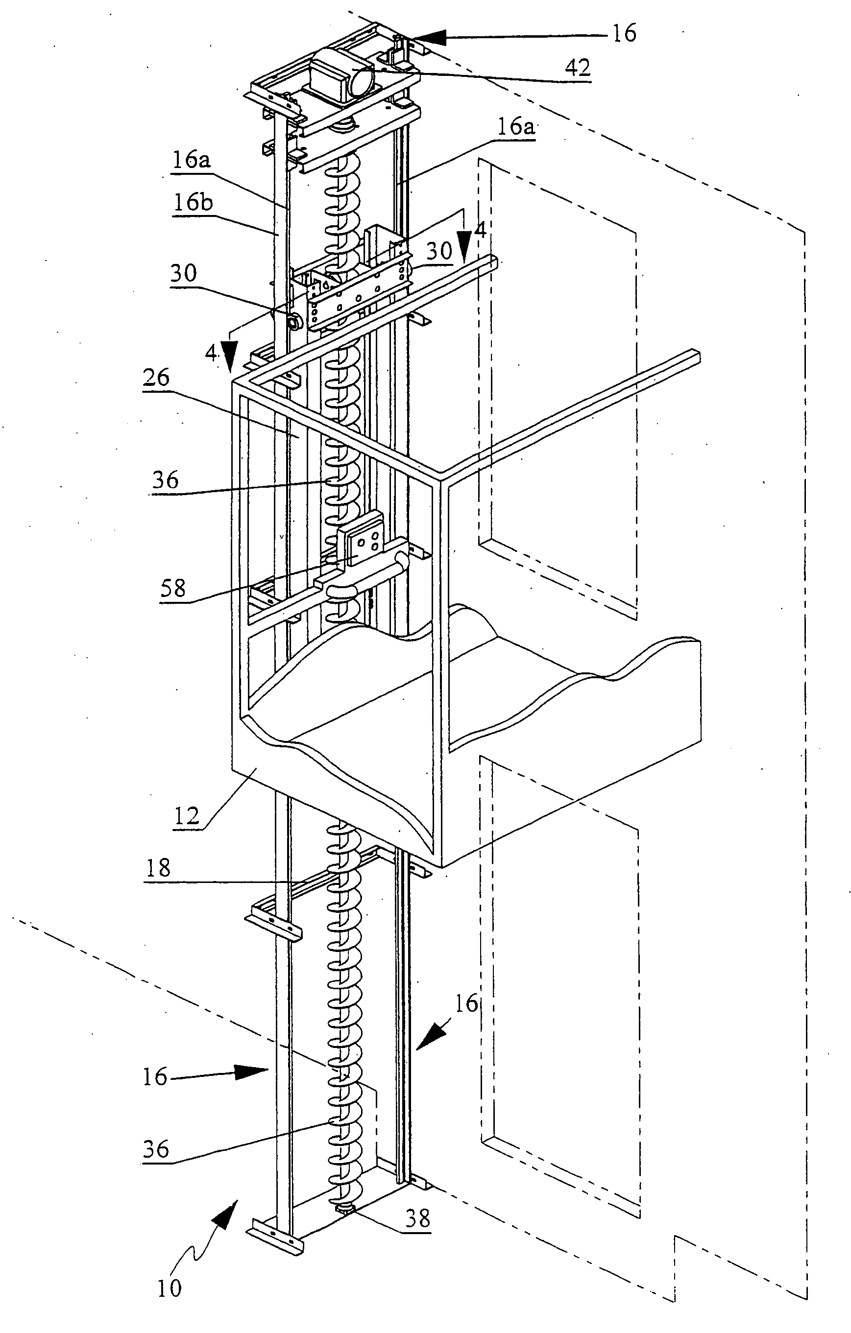
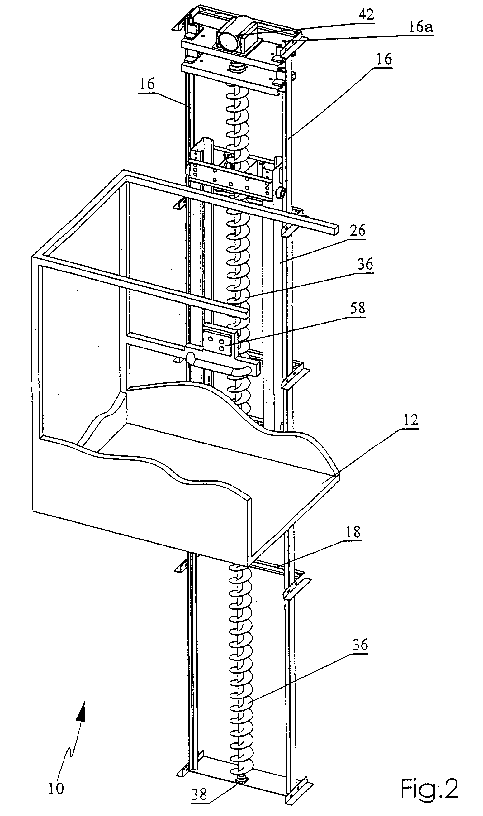
[0039] With reference to the drawing figures, wherein similar characters of reference denote corresponding parts in each view, elevator 10 has a platform or car 12, which is slidably mounted for reciprocal vertical movement on guide rails 16. Rails 16 have a bearing member 16a and side faces 16b. Rails 16 are securely fastened to supporting brackets 18 so as to be secured parallel and spaced apart. Brackets 18 may be mounted by welding or bolting or the like to either external supporting members (not shown) where the elevator is self-supporting, or to building frame members where the elevator is attached to a structure.

[0040] Elevator car 12 has a vertically disposed supporting carriage or carriage frame 26 mounted between for translation parallel to guide rails 16. Frame 26 includes side brackets 26a and cross brackets 26b. Guide wheels 30 are mounted in transversely spaced apart pairs at the upper and lower corners of each side bracket 26a. Rail 16 is sandwiched between the upper...


PUM


Abstract

A helical screw lift system for an elevator includes a rigid vertical frame having at least one rigid vertical rail; and a single elongate helical screw having an inclined helical flight. The screw is rotatably vertically mounted to the frame at opposite ends of the screw. A motor mounted to the frame rotates the screw. A carriage is mounted to the vertical rail for vertical translation. An elevator platform is mounted to the carriage. Four wheels are rigidly mounted cantilevered from the carriage. The wheels engage and bear down on the helical flight of the screw for rolling translation therealong when the screw is rotated about its longitudinal axis so as to raise or lower the elevator platform.

Description

CROSS-REFERENCE TO RELATED APPLICATION [0001] This is a Continuation-in-Part Patent Application of U.S. patent application Ser. No. 10 / 887,875 filed Jul. 12, 2004 which claims priority from U.S. Provisional Patent Application Ser. No. 60 / 492,995 filed Aug. 7, 2003 entitled Helical Screw Lift System for an Elevator.FIELD OF THE INVENTION [0002] This invention relates to a lift system which employs a single helical screw for reciprocal vertical movement of a platform or elevator car between landings. BACKGROUND OF THE INVENTION [0003] The rapid vertical transportation of persons and materials between multiple floors or landings has long been accomplished by conventional elevator systems which utilize several well known drive systems such as hydraulic systems and traction or winch systems Most of these systems are intended for accommodating multiple passengers between multiple floors such as in office buildings and apartments. [0004] As the proportion of elderly persons continues to in...

Claims


Application Information

Patent Timeline
Patent Type & Authority Applications(United States)
IPC IPC(8): B66B9/02
CPCB66B9/025
Inventor NIELSEN, KAJ GUY
Owner NIELSEN KAJ GUY
Learn More