Bicycle carrier

a bicycle and carrier technology, applied in the field of bicycle carriers, can solve the problems of not being universally applicable to substantially all bicycles, difficult to achieve the goal of versatility of application to diverse vehicle types and designs, and cumbersome and difficult use by all members of the family. , to achieve the effect of reducing the amount of effort, and reducing the difficulty of transportation

Inactive Publication Date: 2007-01-11
WITCZAK JOHN
View PDF16 Cites 33 Cited by
  • Summary
  • Abstract
  • Description
  • Claims
  • Application Information

AI Technical Summary

Benefits of technology

[0007] An advantage of the present invention is that the carrier presents support arms for the relatively upper perimeters of the bicycle wheels, which can be placed thereon individually at ground level with a minimum of effort.
[0008] Another advantage of the present invention is that the manner of supporting the wheels affords considerable versatility for accommodating a wide variety of bicycle designs for all family members.
[0009] Yet another advantage of the present invention is that the support arms are readily stowable in a parked, non-use, stowed position in relatively close adjacency to the roof of the vehicle and are manually movable into a working deployed position from ground level with a minimum of effort, the arms being lockable in the parked and the deployed position. Release of the arms from the locked condition requires a simple movement. The spaced disposition of the arms is conveniently variable to cater for differing bicycle dimensions.
[0010] Another advantage of the present invention is that the movement of the arms in the deployed position into a hitching mode wherein the bicycle may be mounted on the arms is effectively controlled by means of a damper thus preventing any sudden movement that might compromise safety.
[0011] A still further advantage of the instant invention is that the means for clamping the wheels in position are of relatively simple construction with quick release mechanisms for ease of use.
[0012] According to an aspect of the present invention, there is provided a bicycle carrier for releasably securing a bicycle to a roof rack of a vehicle, the bicycle carrier comprising a base frame securably mountable on the roof rack, a beam extending adjacent the roof rack longitudinally of the base frame and of the vehicle and rotatable relative thereto along a beam longitudinal axis lengthwise of the vehicle, a support arm spaced apart along the beam and pivotable relative thereto at a first end thereof between a stowed position adjacent the base frame and a deployed position, detent means associated with the support arm to retain the arm in the deployed position, first wheel support means disposed at a free second end of the support arm and adapted in use to clamp an upper region of a respective wheel of the bicycle to the arm, and second wheel support means provided on the beam for securing a lower region of the respective wheel to the beam, damper means associated with the beam for damping its rotational movement.

Problems solved by technology

One of the problems attendant upon current and conventional bicycle carriers is that of being cumbersome and difficult to use by all members of the family.
Additionally, given the differing designs available for bicycles manifest in varied frame shapes and configurations, problems have arisen in terms of carriers not being universally applicable for substantially all bicycles.
Furthermore, versatility of application to diverse vehicle types and designs has proven to be a difficult goal to attain.
In particular, it will be observed that the proposed structure is provided with complicated anchorages for securing the mounting legs used for supporting the bicycle in the carriage position, upright atop of the carrier and the vehicle.
Clearly for bicycles intended for female riders, such an arrangement would be inappropriate, thus yielding the carrier limited in its scope of usage.
Disadvantages of the Groves' approach are at least two-fold in that a special drive array is required to actuate the lift, and the clamping of the upper region of the bicycle is upon parts that are variably located dependent upon the configuration of the bicycle.

Method used


Image

  • Bicycle carrier
  • Bicycle carrier
  • Bicycle carrier

Examples


Embodiment Construction

[0035] With reference to the annexed drawings the preferred embodiments of the present invention will be herein described for indicative purpose and by no means as of limitation.

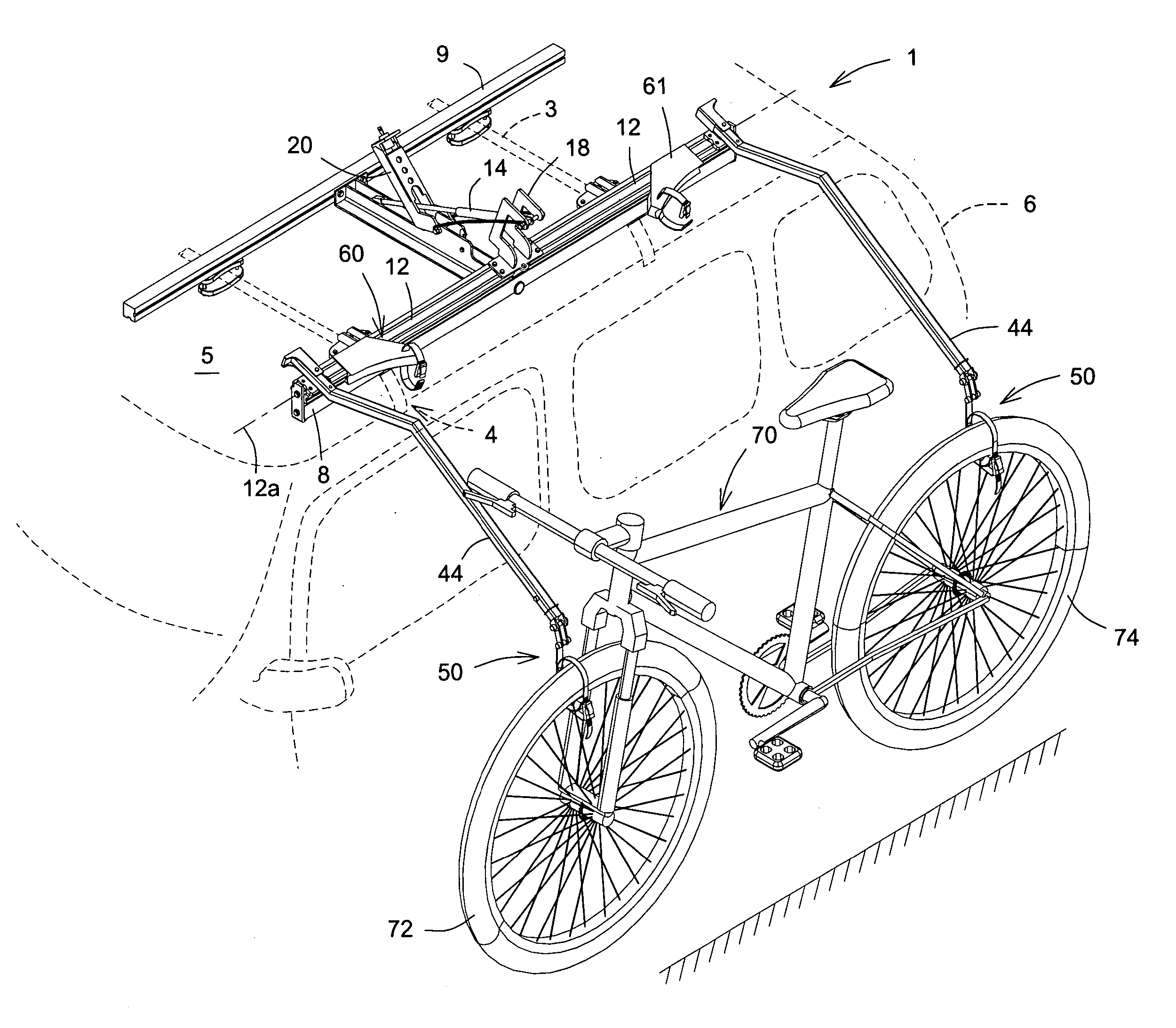
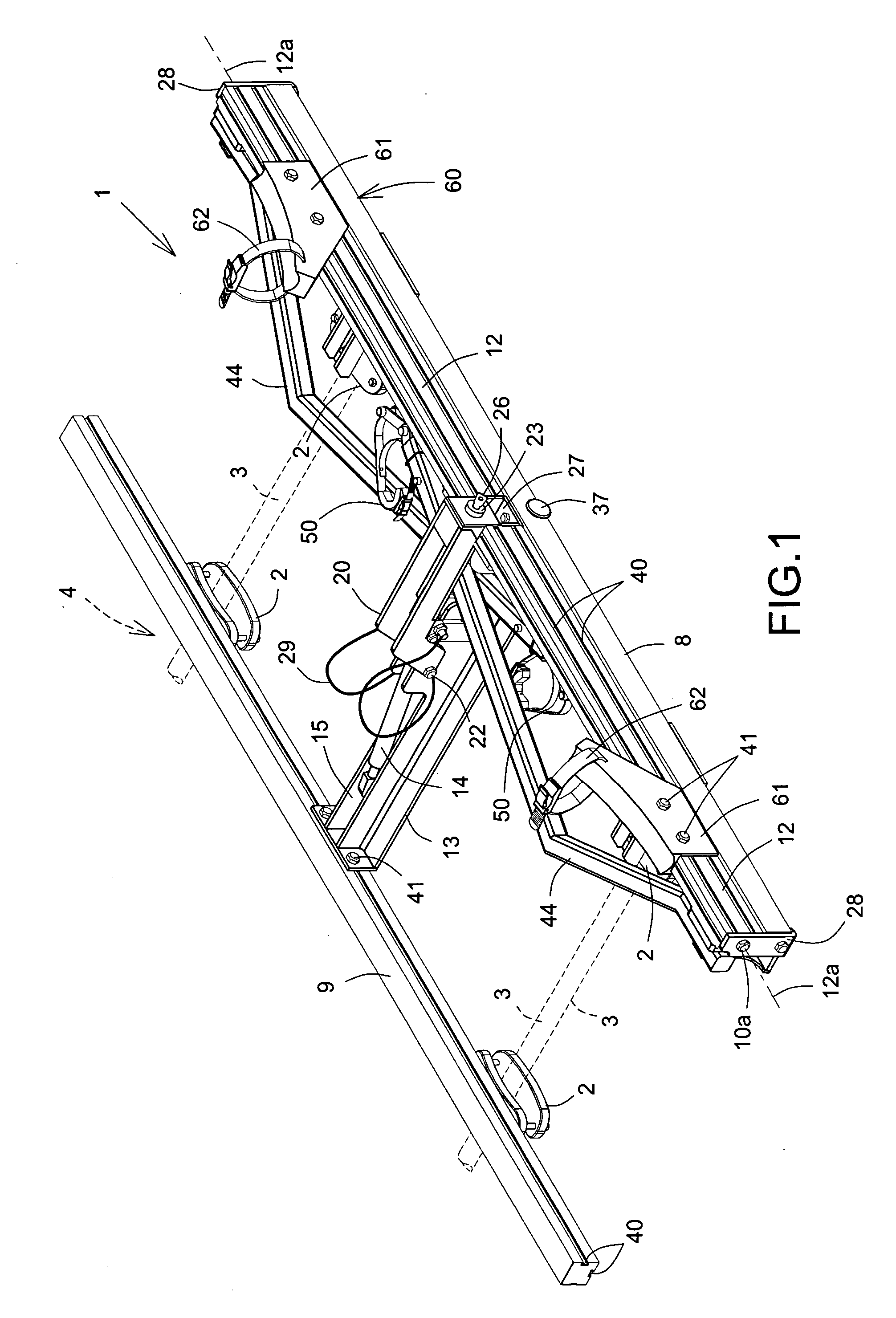
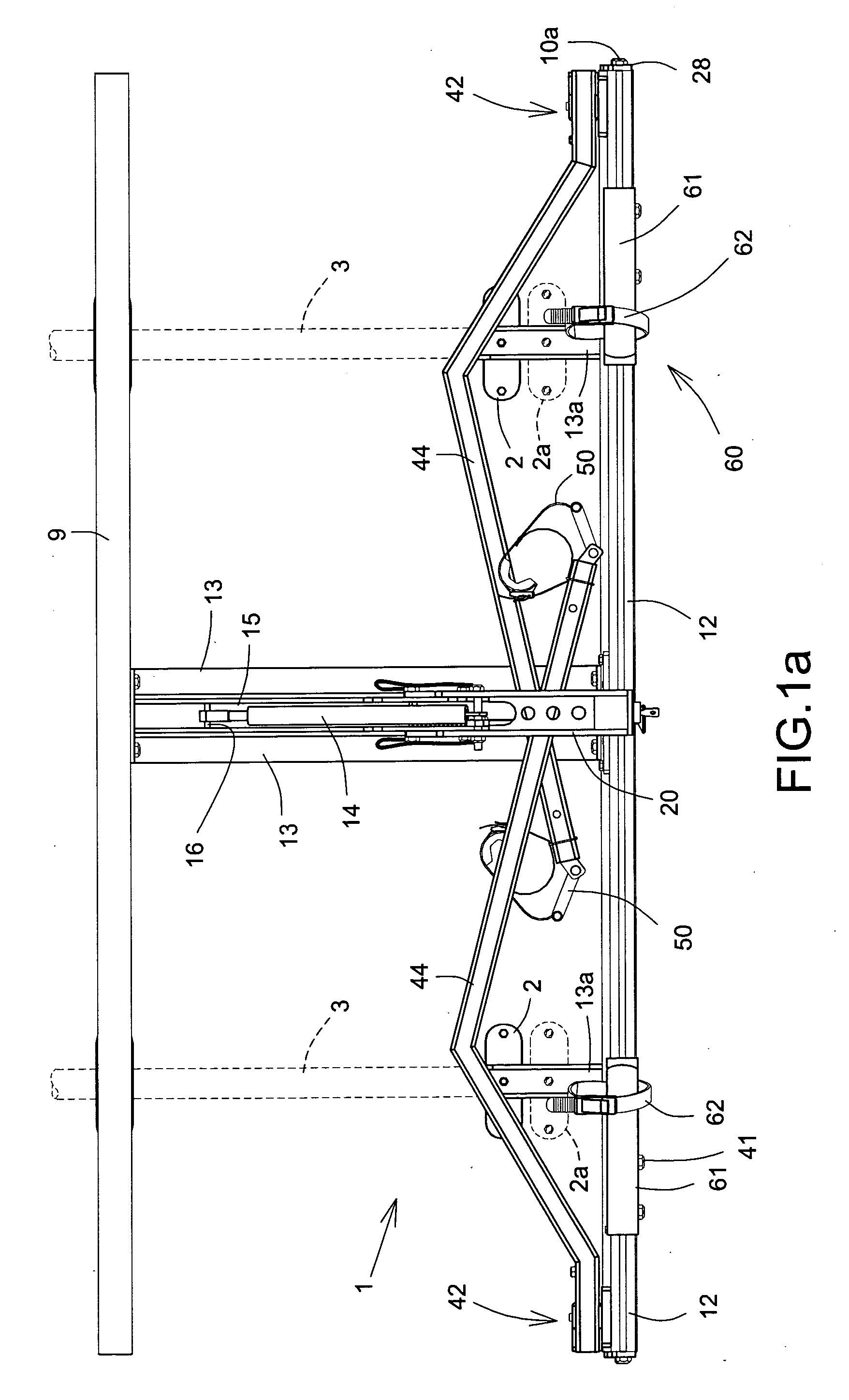
[0036] Referring to the figures, there is shown a bicycle carrier 1 in accordance with an embodiment of the present invention for releasably securing a bicycle 70 to a roof rack 4 mounted on the roof 5 of a vehicle 6 (see FIG. 5). The carrier 1 is typically provided with four mounts 2 for securing to transversal bars 3 of the roof rack 4. The carrier 1 includes a base frame 8 extending longitudinally of the vehicle 6, the base frame 8 being provided with a central hinge pin 10, and typically two end hinge pins 10a collinear to central hinge pin 10, mounted on a central bracket 27 and end brackets 28, respectively, (see FIGS. 1, 2 and 3) about which a beam 12 (or typically two half-beams as shown in the figures) is rotatable about a beam longitudinal axis 12a between a beam parked position when the carrier 1...


PUM


Abstract

A bicycle carrier provides a rotatable beam on which are mounted foldable support arms having first wheel support means for engaging and entrapping the upper peripheral regions of the wheels of a bicycle, the beam being rotatable into a bicycle carriage mode vertically above the vehicle when the arms are in an arm deployed position and lockable in that position. Resiliently-biased detent means are associated with the support arms mountings for positively locking the arms in the deployed position in relation to the beam, simple movement against the bias effecting disengagement.

Description

FIELD OF THE INVENTION [0001] The present invention concerns a bicycle carrier of the kind for use on a vehicle for the carriage of at least one bicycle externally thereof. In particular, the invention has reference to such a carrier for fixture to the vehicle roof for safe and secure stowage of a bicycle during transportation and provided with means for facilitating the mounting and dismounting of the bicycle in relation to the carrier and the vehicle. BACKGROUND OF THE INVENTION [0002] Bicycle carriers are legion in terms of design and mode of use and with the burgeoning of interest in cycling as a pastime and indeed a sport for the masses, many and varied types of carriers have been proposed for all manner of vehicles. With the introduction of family vehicles capable of transporting a relatively large number of people, the need to address the practicalities of bicycle carriers has become more pressing. One of the problems attendant upon current and conventional bicycle carriers i...

Claims


Application Information

Patent Timeline
Patent Type & Authority Applications(United States)
IPC IPC(8): B60P9/00B60R9/00
CPCB60R9/10B60R9/042
Inventor WITCZAK, JOHN
Owner WITCZAK JOHN
Why Eureka
Try Eureka