Radar device

a technology of a radar and a detection device, which is applied in the direction of measurement devices, instruments, and devices using reradiation, can solve the problems of difficult access to high-accurate observed values, and achieve the effects of stable tracking, high accuracy and highly-accurate observed values

Inactive Publication Date: 2007-01-11
MITSUBISHI ELECTRIC CORP
View PDF6 Cites 41 Cited by
  • Summary
  • Abstract
  • Description
  • Claims
  • Application Information

AI Technical Summary

Benefits of technology

[0008] Therefore, the radar device has an effect that stable tracking with high accuracy is made possible, even in a situation in which, in particular, a plurality of external targets are close to each other, and are driving in parallel at a constant velocity, so that highly-accurate observed values are not easily-obtainable.

Problems solved by technology

Therefore, the radar device has an effect that stable tracking with high accuracy is made possible, even in a situation in which, in particular, a plurality of external targets are close to each other, and are driving in parallel at a constant velocity, so that highly-accurate observed values are not easily-obtainable.

Method used


Image

  • Radar device
  • Radar device
  • Radar device

Examples


embodiment 1

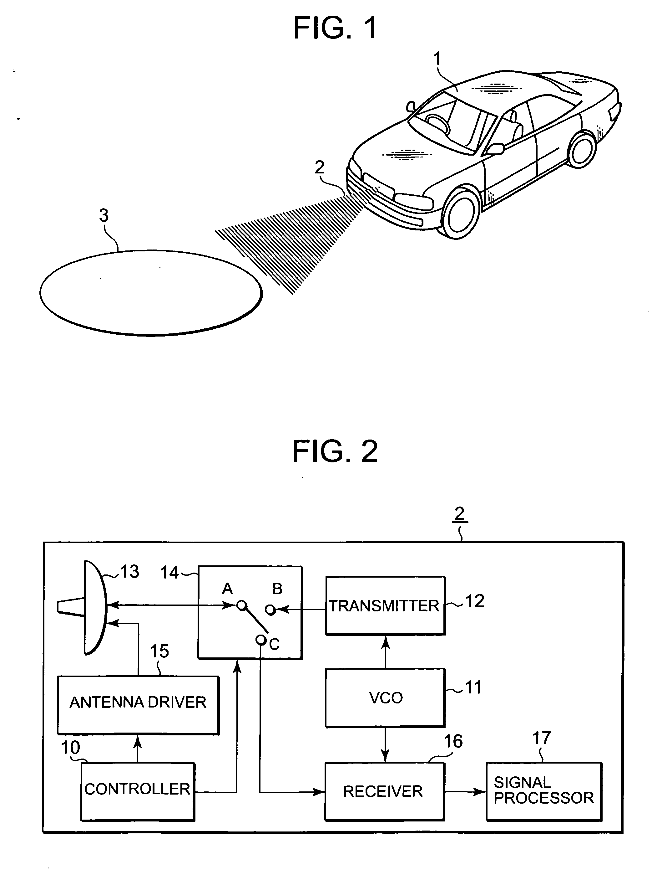
[0023]FIG. 1 illustrates a car equipped with a radar device according to Embodiment 1 of the present invention. In the figure, the radar device 2 according to Embodiment 1 of the present invention is installed in the front of the car 1. The radar device 2 radiates a beam forward from the car 1. A portion of the radiated beam is reflected by an object 3 that is located in front of the car 1, and comes back to the radar device 2. The radar device 2 receives the reflected beam, and performs signal processing, to detect the distance to the object 3, and the velocity and the direction of the object 3. According to the above-obtained information on the object 3, the car 1 performs control such as automatic braking for avoiding a collision, and adjusting seat belts in preparation for a collision. Consequently, it largely contributes to dramatically enhance safety of the car 1.

[0024]FIG. 1 is a block diagram illustrating the configuration of the radar device 2. The radar device 2 is a rada...

embodiment 2

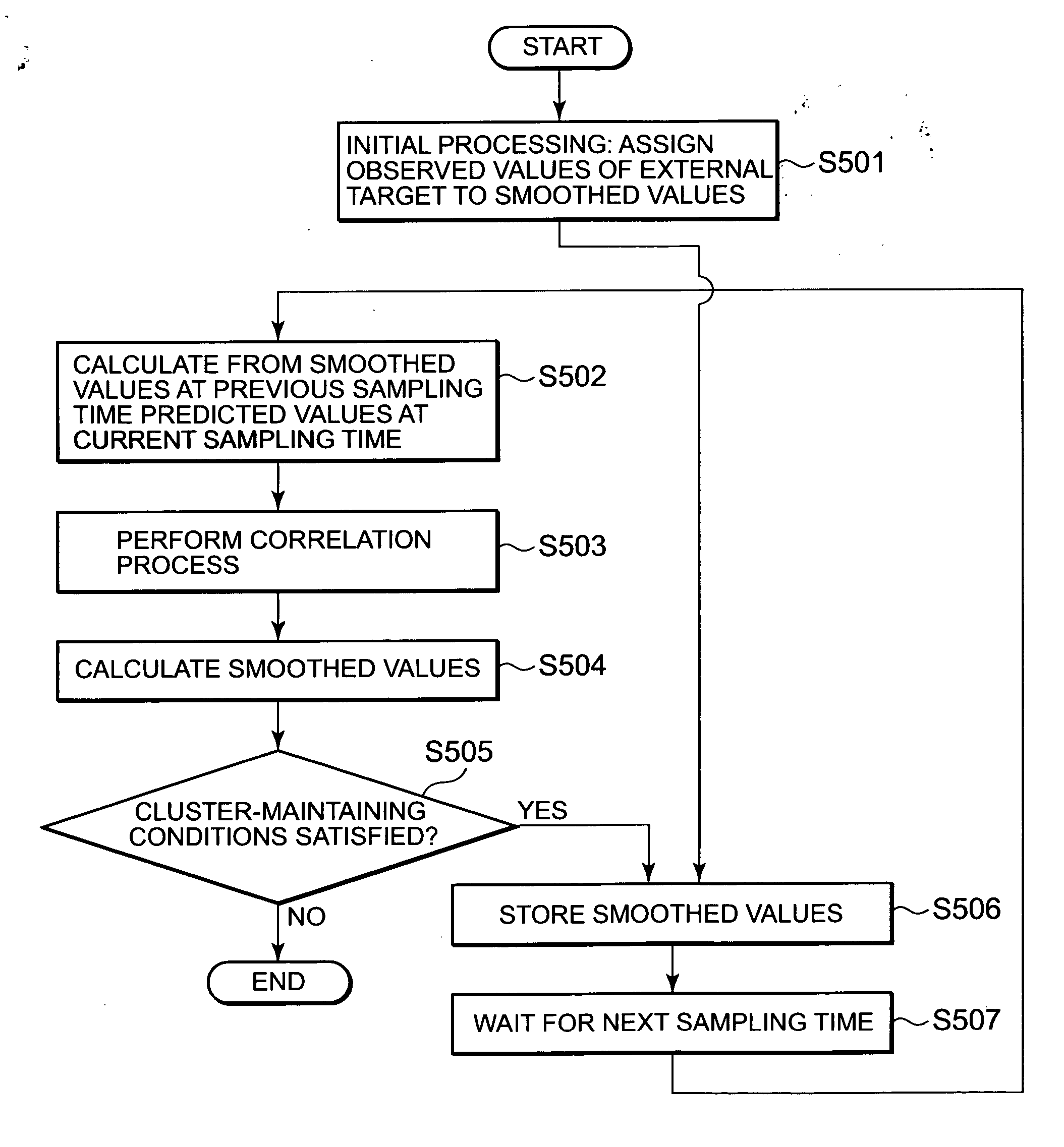
[0094] In Embodiment 1, clusters are formed from targets that are close to each other, and the filtering for the targets that belong to the clusters is differently designated from the filtering for targets that do not belong to any of the clusters. In addition, in cases in which targets to be observed are close to each other, and move in parallel at a constant velocity, the tracking processing can be performed while regarding a cluster as a single target. A radar device according to Embodiment 2 of the present invention has such a feature.

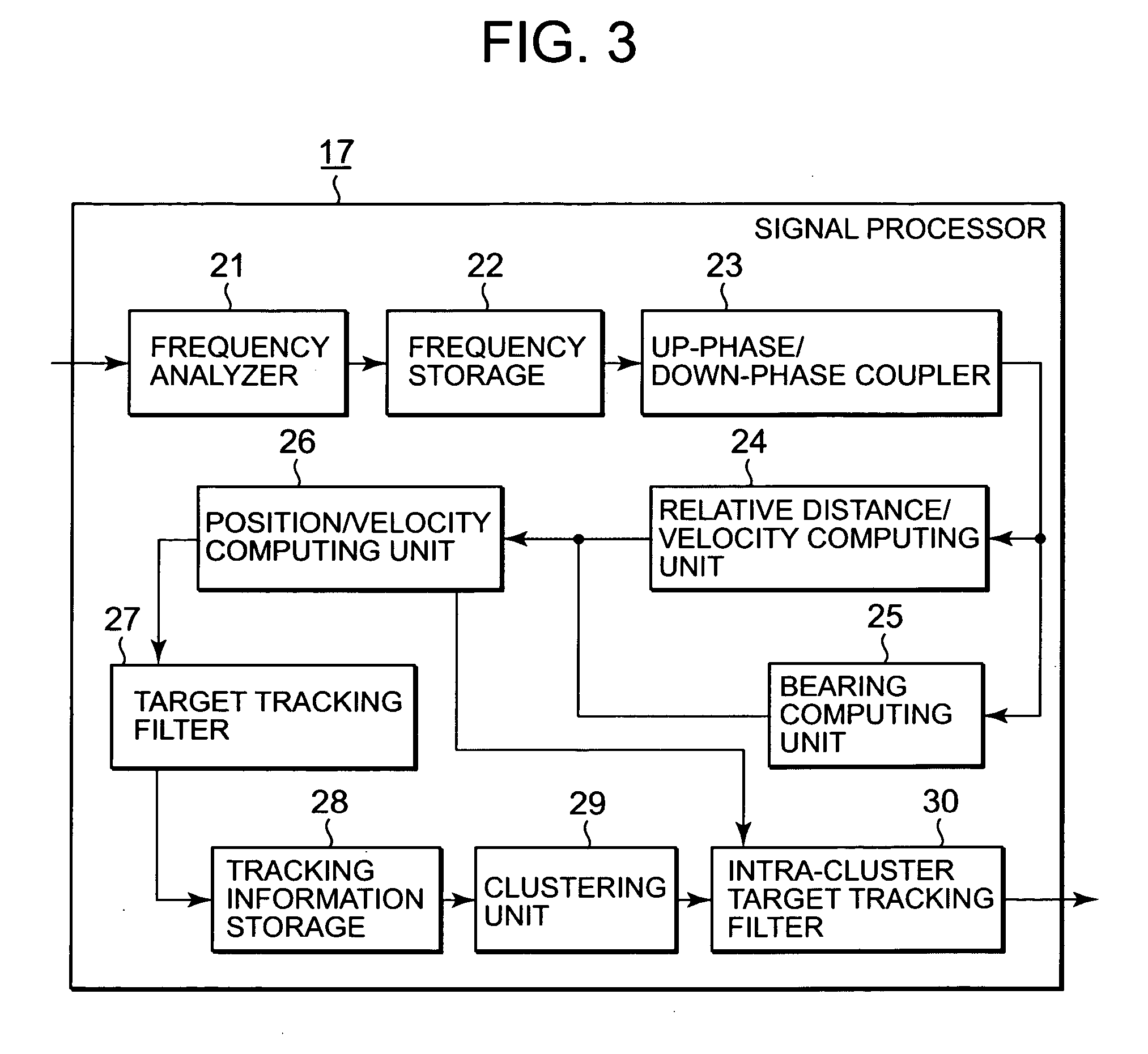
[0095] The entire structure of the radar device according to Embodiment 2 of the present invention is illustrated in the block diagrams in FIG. 1 and FIG. 2 as in Embodiment 1. Because the components with the same numerals as in Embodiment 1 are similar to the corresponding components in Embodiment 1, the explanation will be omitted. In addition, the detailed configuration of a signal processor 17 is illustrated in a block diagram in FIG. 11.

[009...


PUM


Abstract

A radar device tracks with a high accuracy positions and velocities of a plurality of external targets that are close to each other and whose observed direction values are likely to be low. The radar device includes: a target tracking filter for calculating relative distances and relative velocities of a plurality of external targets by signal-processing received signals from an antenna, for calculating the directions of the plurality of external targets by combining, among beam patterns radiated by the antenna, adjacent beam patterns that partially overlap, and for obtaining, from the directions and the relative distances and velocities, observed position values and observed velocity values of the plurality of external targets, to calculate, from the observed position values and the observed velocity values, smoothed values of the position and velocity for each of the external targets; and an intra-tracking-processing-cluster target tracking filter for forming a cluster from the plurality of external targets that are close to each other, for creating gates for the external targets in the cluster, different from those in the target tracking filter, and for performing a correlation process on the observed values of the external targets based on the gates.

Description

TECHNICAL FIELD [0001] The present invention relates to radar devices, and to a technology for, particularly when targets to be tracked are close to each other, accurately tracking the targets. BACKGROUND ART [0002] A sequential-lobing system and a monopulse system are known as technologies for observing the direction of a target by combining a plurality of beam patterns. These are methods of estimating the direction of a target by calculating the difference in target images in adjacent beam patterns. In addition, using a pulse Doppler radar system or an FMCW radar system, the relative distance to the target and the relative velocity of the target can be obtained. Therefore, by combining these systems (for instance, the sequential-lobing system and the FMCW radar system), the position and the velocity of the target with respect to the ground surface can be calculated. [0003] However, these methods assume that a single target is present. The conventional methods cannot deal with a ca...

Claims


Application Information

Patent Timeline
Patent Type & Authority Applications(United States)
IPC IPC(8): G01S13/42G01S7/28G01S13/931G01S13/34G01S13/44G01S13/66G01S13/72
CPCG01S13/34G01S13/42G01S2013/9375G01S13/931G01S13/726G01S13/44G01S13/584G01S13/723G01S2013/93185G01S2013/93271
Inventor KIBAYASHI, NORIKOITO, MASAYOSHI
Owner MITSUBISHI ELECTRIC CORP
Why Eureka
Try Eureka