Method and apparatus for displaying workflow

a workflow and workflow technology, applied in the field of workflow display, can solve the problems of user difficulty in finding the discrete box in which the trouble occurred, and the user is not able to immediately take corrective actions, so as to save resources

Active Publication Date: 2007-01-11
KONICA MINOLTA BUSINESS TECH INC
View PDF12 Cites 18 Cited by
  • Summary
  • Abstract
  • Description
  • Claims
  • Application Information

AI Technical Summary

Benefits of technology

[0010] The inventors of the present invention are developing a workflow system composed of a document processor for linking discrete Boxes each associated with a different pro

Problems solved by technology

However, when a trouble (error) occurs somewhere in a process sequence being executed in the workflow system, it is difficult for the user to locate a discrete Box in which the trouble occurred.
Acco

Method used


Image

  • Method and apparatus for displaying workflow
  • Method and apparatus for displaying workflow
  • Method and apparatus for displaying workflow

Examples


embodiment

[0056] Hereinafter, a description is given first to the structure of a workflow system. Then, a description is given to a workflow display method according to an embodiment of the present invention.

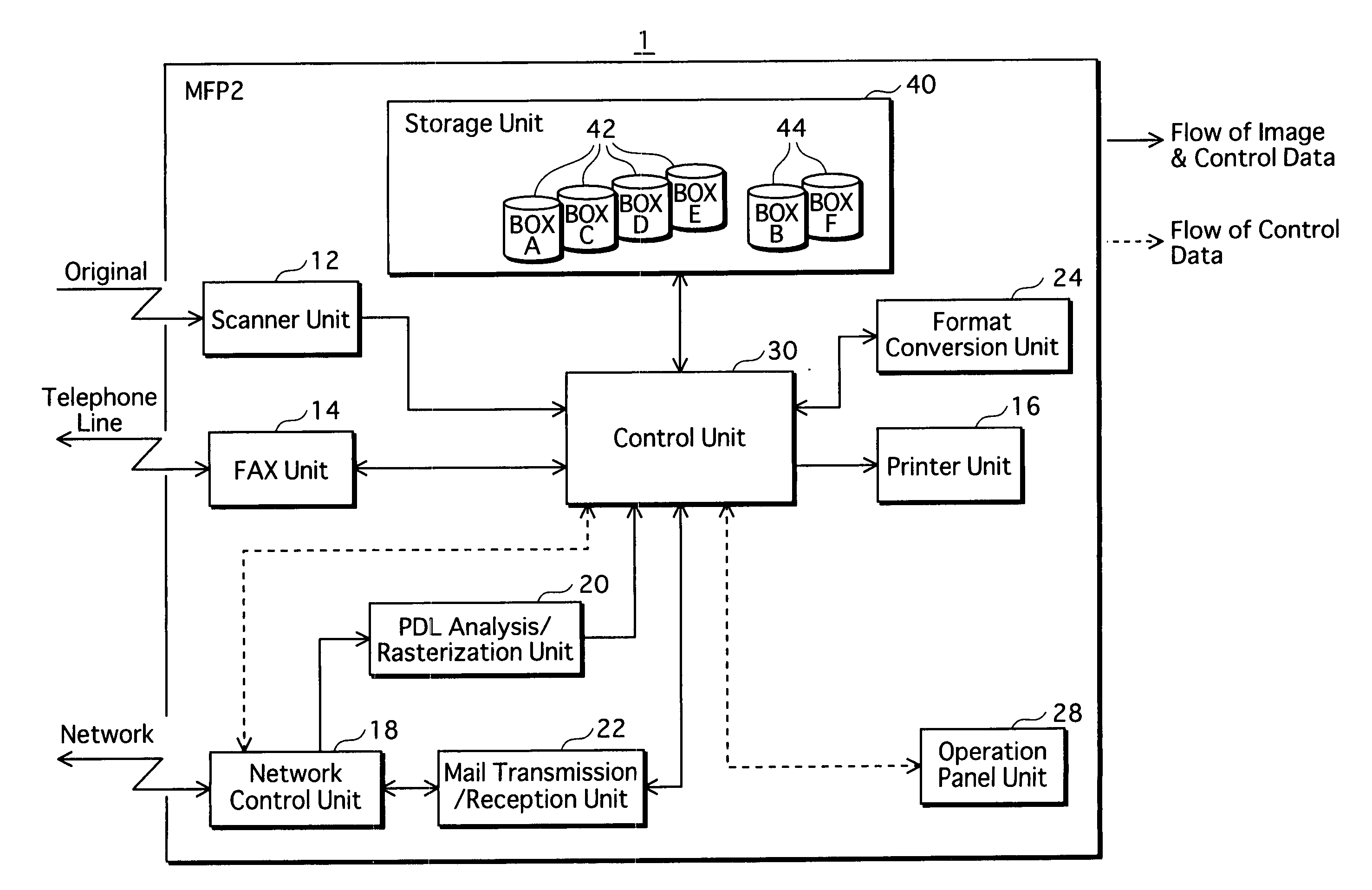
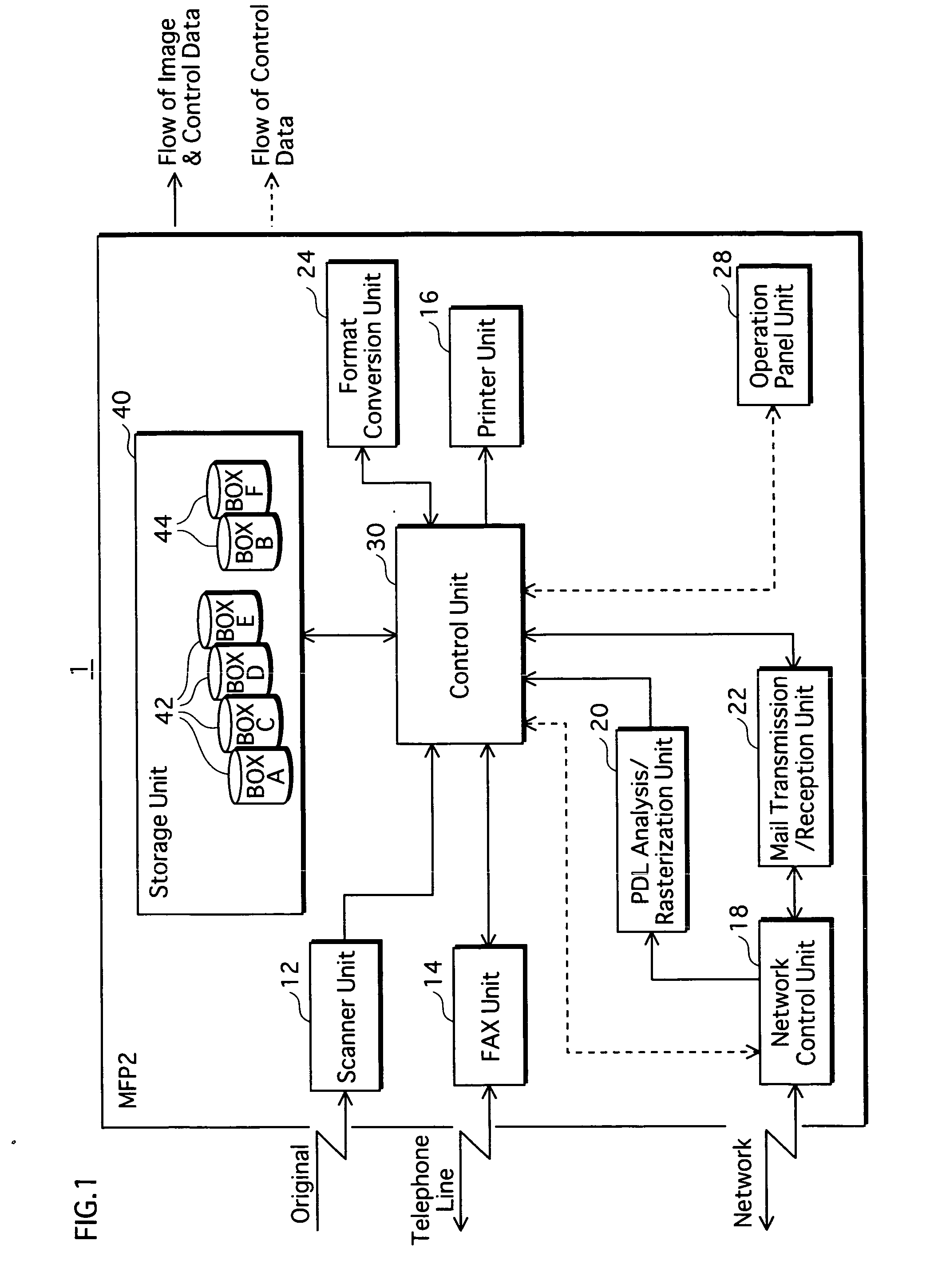
[0057]FIG. 1 is a block diagram showing the overall configuration of a workflow system 1.

[0058] The workflow system 1 assists users with routine tasks by automatically controlling processes in the sequence set in advance. The workflow system 1 is composed of an MFP 2, which is a document processor.

[0059] The MFP 2 includes a scanner unit 12, a FAX unit 14, a printer unit 16, a network control unit 18, a PDL analysis / rasterization unit 20, a mail transmission / reception unit 22, a format conversion unit 24, an operation panel unit 28, a control unit 30, and a storage unit 40. Hereinafter, a description is given to each unit.

[0060] The scanner unit 12 reads an original document placed on, for example, a sheet feeder to generate image data, and passes the image data to the control unit 30...

modification 1

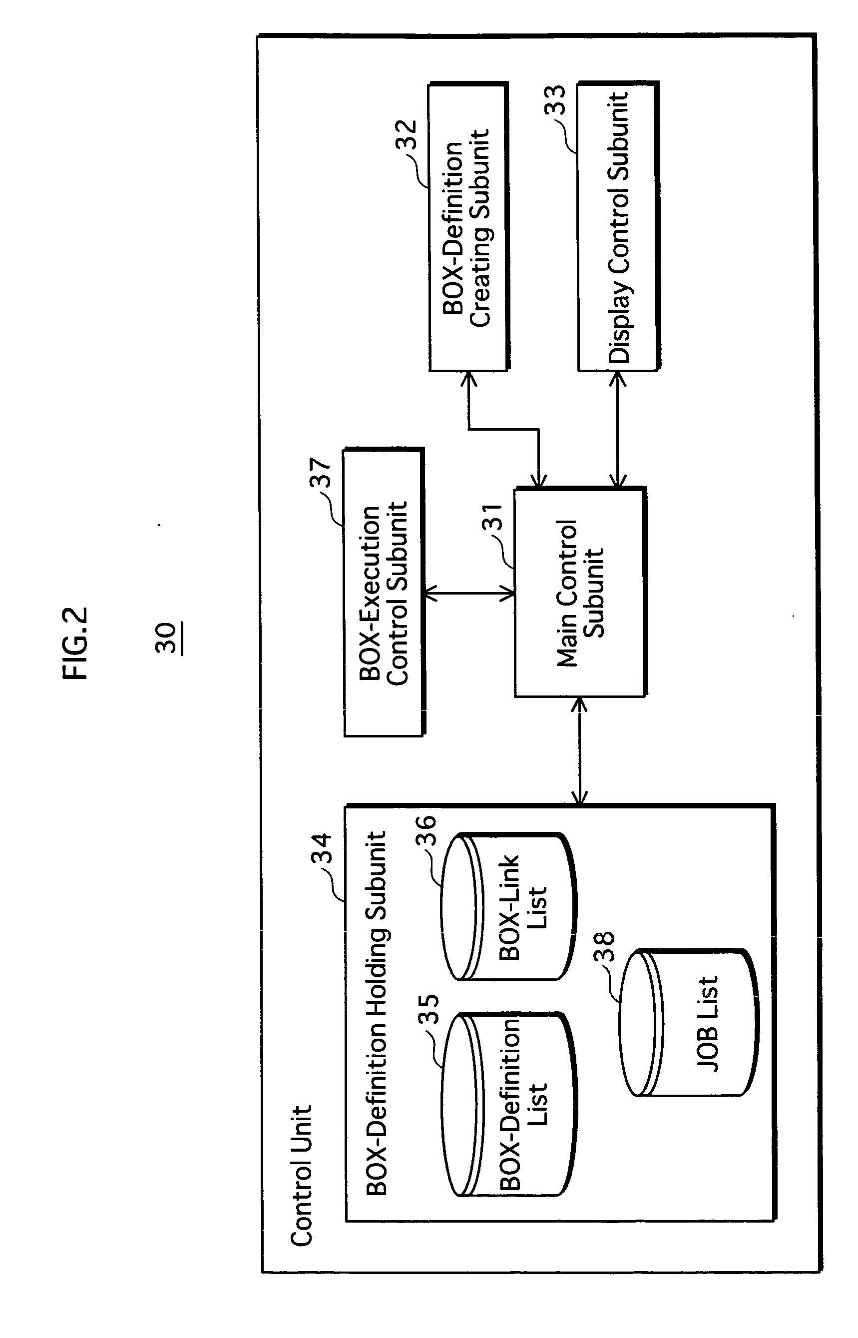
[0213] According to the above embodiment, the Box-definition holding subunit 34 in the control unit 30 collectively holds the Box-definition list 35 and the Box-link list 36 and manages both the lists. Yet, it is applicable to distribute the lists among the Boxes.

[0214] FIGS. 25 each show the data structure of a Box according to the modification 1. More specifically, FIG. 25A shows the data structure of a discrete Box 42, and FIG. 25B shows the data structure of a compound Box 44.

[0215] The discrete Box 42 includes document data 42a and Box definition information 42b. Similarly to the Box-definition list 35 shown in FIG. 3, the Box definition information 42b is composed generally of information showing (i) the attribute of the Box, (ii) a document input source, (iii) a document output destination, and (d) a process associated with the Box.

[0216] The document data 42a may be any data allowing the document to be managed. For example, the document data 42a may be the contents of the...

modification 2

[0218] According to the above embodiment, it is displayed in the step S604 simply whether each job is currently being processed or not (See FIG. 21B).

[0219] Alternatively, it is applicable to display the progress in greater detail as shown in FIG. 26. In addition, it is applicable to make arrangement to display the screen shown in FIG. 26 at a touch of “Box A” shown in FIG. 21C.

[0220]FIG. 26 shows an exemplary display screen showing the job state, according to the modification 2. As shown in the figure, the progress of the format conversion (.pdf→.tiff) is displayed as a percentage (50% in the figure), along with the remaining processing time expected to be taken to complete the job (12 sec, in the figure). The expected remaining processing time is calculated with reference, for example, to the history showing the past processing times. By displaying the progress of time-consuming processes, such as the conversion process, the user convenience increases.


PUM


Abstract

A display method for displaying a workflow system composed of a plurality of discrete Boxes each associated with a document process and linked in a predetermined order. The workflow is defined for causing the processes to be sequentially executed. The workflow is displayed using icons representing the Boxes. If execution of the associated process has been completed, an icon representing a corresponding Box is overlaid with oblique lines. If execution of the associated process is currently in process, an icon representing a corresponding Box is overlaid with a graphical representation of a sand timer.

Description

[0001] This application is based on applications No. 2005-199155 and No. 2005-295297 filed in Japan, the contents of which are hereby incorporated by reference. BACKGROUND OF THE INVENTION [0002] (1) Field of the Invention [0003] The present invention relates generally to a method for displaying a workflow. [0004] (2) Description of the Related Art [0005] MFPs (Multi-Function Peripherals) are document processors that include, for example, printer, FAX, and copier capabilities. Some of such conventional document processors are known to have a Box function which is associated in advance with a process to be executed on a document saved by the respective document processor. [0006] For example, JP patent application publication No. 2004-227476 discloses a document processor having Box functions associated with document processing, such as modification and printing of a document. With a document processor having a Box function, users are allowed to process a document on the document proc...

Claims


Application Information

Patent Timeline
IPC IPC(8): G06F3/12
CPCH04N1/00408H04N2201/0094H04N1/00482H04N1/00432
Inventor KAWABUCHI, YOICHISAKIYAMA, DAISUKEYOSHIDA, OKIHISAYOSHIMURA, TOMONARI
Owner KONICA MINOLTA BUSINESS TECH INC
Why Eureka
Try Eureka