Head gimbal assembly with accessory plate and a method of manufacturing the same

Active Publication Date: 2007-01-11
SAE MAGNETICS (HK) LTD
View PDF2 Cites 7 Cited by
  • Summary
  • Abstract
  • Description
  • Claims
  • Application Information

AI Technical Summary

Benefits of technology

[0006] A main feature of the present invention is to provide a HGA with an access

Problems solved by technology

In addition, forming the individual flexure 32 and the load beam 33 cost much time and money.
In other words, the traditional HGA has a large inertia which results in a bad shock performance.
When an im

Method used


Image

  • Head gimbal assembly with accessory plate and a method of manufacturing the same
  • Head gimbal assembly with accessory plate and a method of manufacturing the same
  • Head gimbal assembly with accessory plate and a method of manufacturing the same

Examples


Example

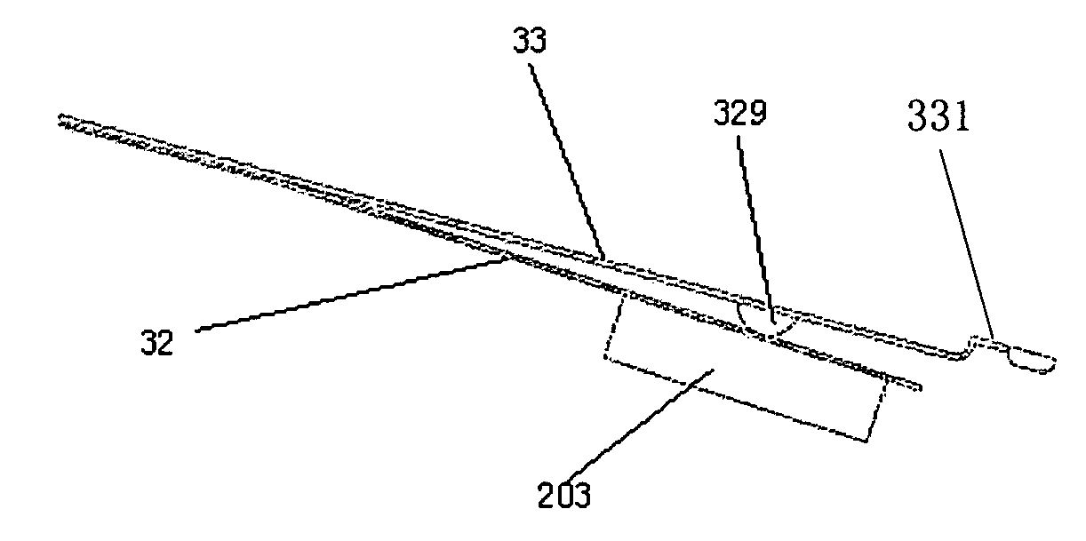
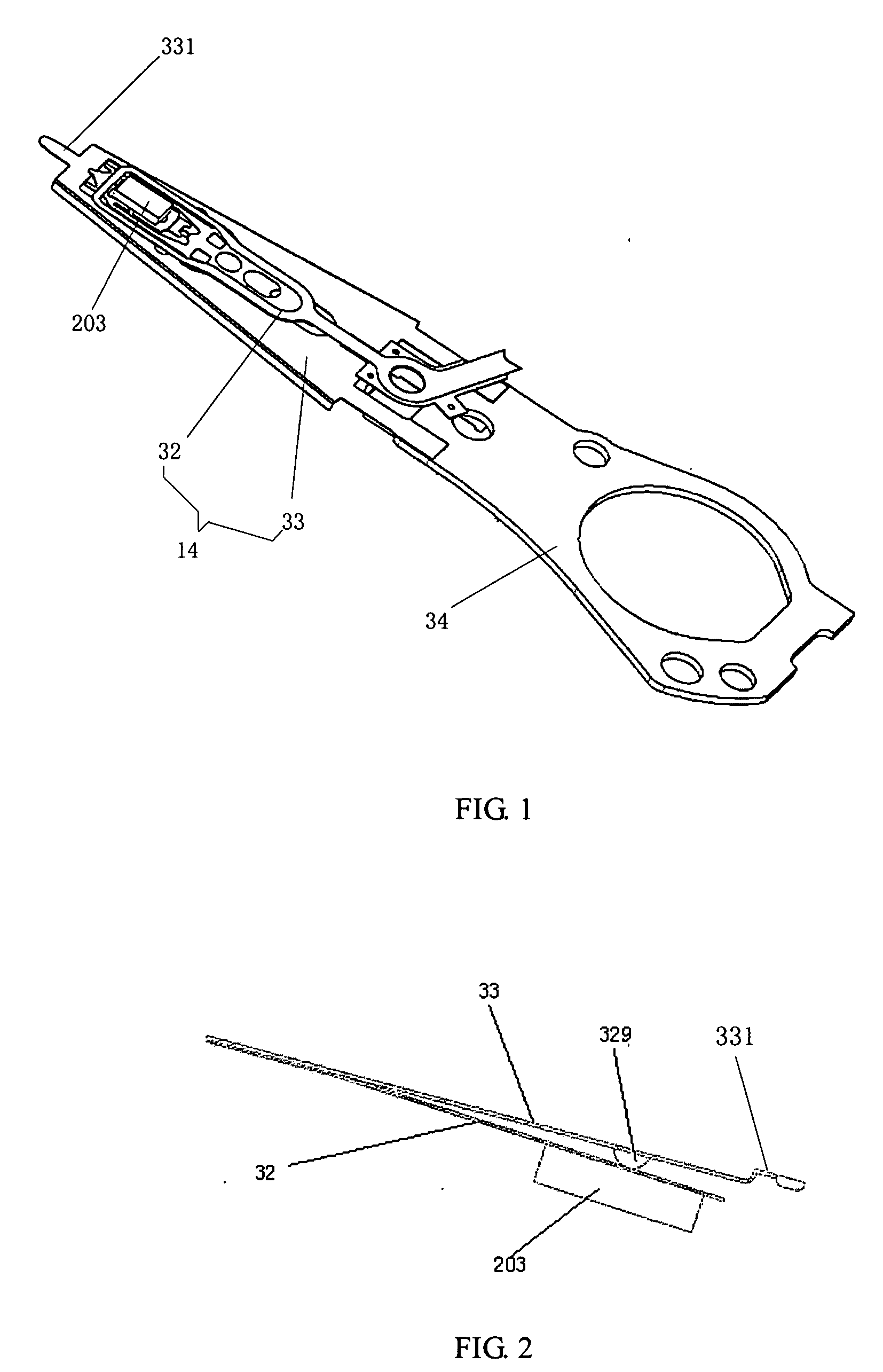
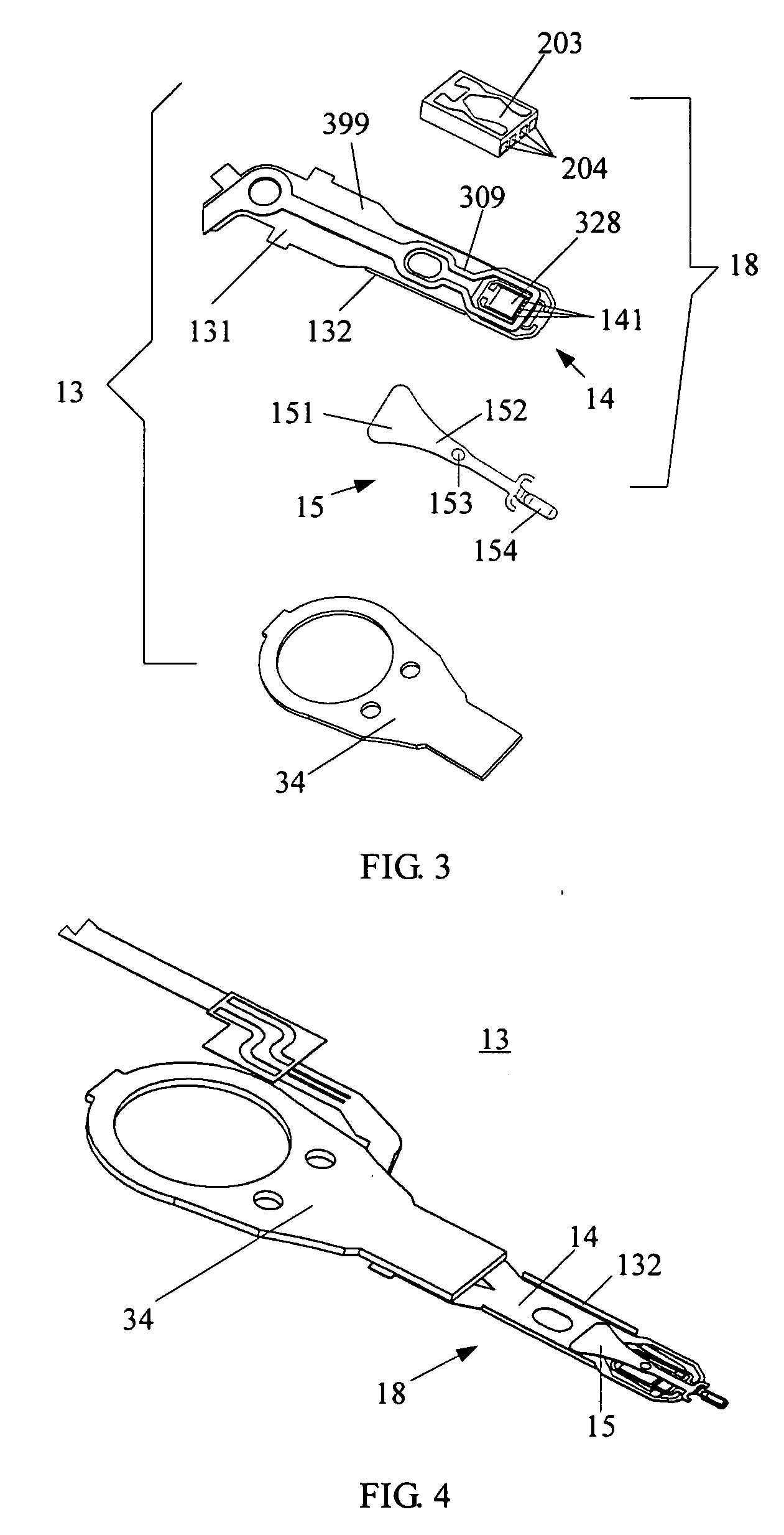
[0023] As indicated above, the instant invention is to provide a HGA with an accessory plate and a method of manufacturing such a HGA to simplify the assembly of the HGA. The HGA comprises a slider; a suspension having a slider holding plate; and an accessory plate mounted on the suspension, which having a dimple to partially hold the slider holding plate. In the invention, the accessory plate is bonded to the suspension after the slider being mounted on the suspension so that the dimple thereon will not influence on the slider's mounting, such as positioning the slider on the suspension, bonding the slider to the suspension and electrically connecting the slider with the suspension. In an embodiment, the accessory plate has a lift tab to engage with a ramp. Several example embodiments of the HGA with an accessory plate, a head stack assembly (HSA) with such an HGA of the invention will now be described.

[0024] Referring to FIGS. 3-4, according to an embodiment of the present invent...


PUM


Abstract

A head gimbal assembly, including a slider, a suspension having a slider holding plate, and an accessory plate mounted on the suspension having a dimple to partially hold the slider holder plate.

Description

FIELD OF THE INVENTION [0001] The present invention relates to head gimbal assemblies (HGAs) and disk drive units, and particularly to a head gimbal assembly with accessory plate and a method of manufacturing such a head gimbal assembly. BACKGROUND OF THE INVENTION [0002] Disk drives are information storage devices that use magnetic media to store data. A typical disk drive unit in related art comprises a magnetic disk and a head stack assembly (abbreviated as “HSA”). The magnetic disk is mounted on a spindle motor which causes the magnetic disk to spin. Sliders on the HSA are flying above the magnetic disk to read data from or write data to the magnetic disk. [0003] The conventional HSA includes a rigid drive arm, at least one suspensions which are fixed to a tip end of the drive arm, and sliders mounted to a top end section of each of the suspensions (the suspension with a slider is generally called a “HGA”). The HSA is constructed so that a load applied to the slider in a directi...

Claims


Application Information

Patent Timeline
IPC IPC(8): G11B5/48
CPCY10T29/49027G11B5/4826
Inventor YANG, HUAIZHOU, HAIMINGFENG, XIANWEN
Owner SAE MAGNETICS (HK) LTD
Why Eureka
Try Eureka