
Spool piece termination structure, a connection arrangement comprising such a termination structure and a pipeline termination

Active Publication Date: 2007-01-11
VETCO GRAY SCANDINAVIA
View PDF14 Cites 28 Cited by
  • Summary
  • Abstract
  • Description
  • Claims
  • Application Information

AI Technical Summary

Benefits of technology

[0005] The object of the present invention is to make possible subsea connection of a pipeline to a spool piece, without requiring any complex and / or bulky equipment to be attached to the pipeline hub before it is descended into the sea from a surface vessel.
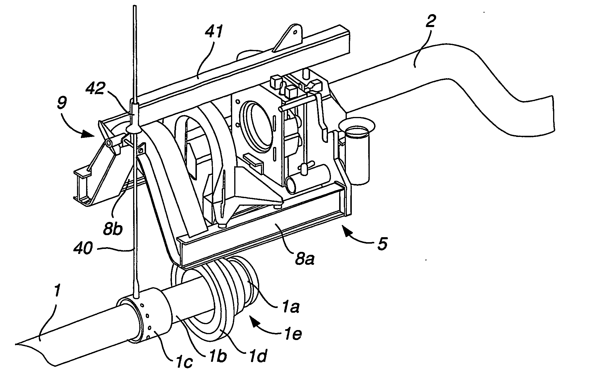
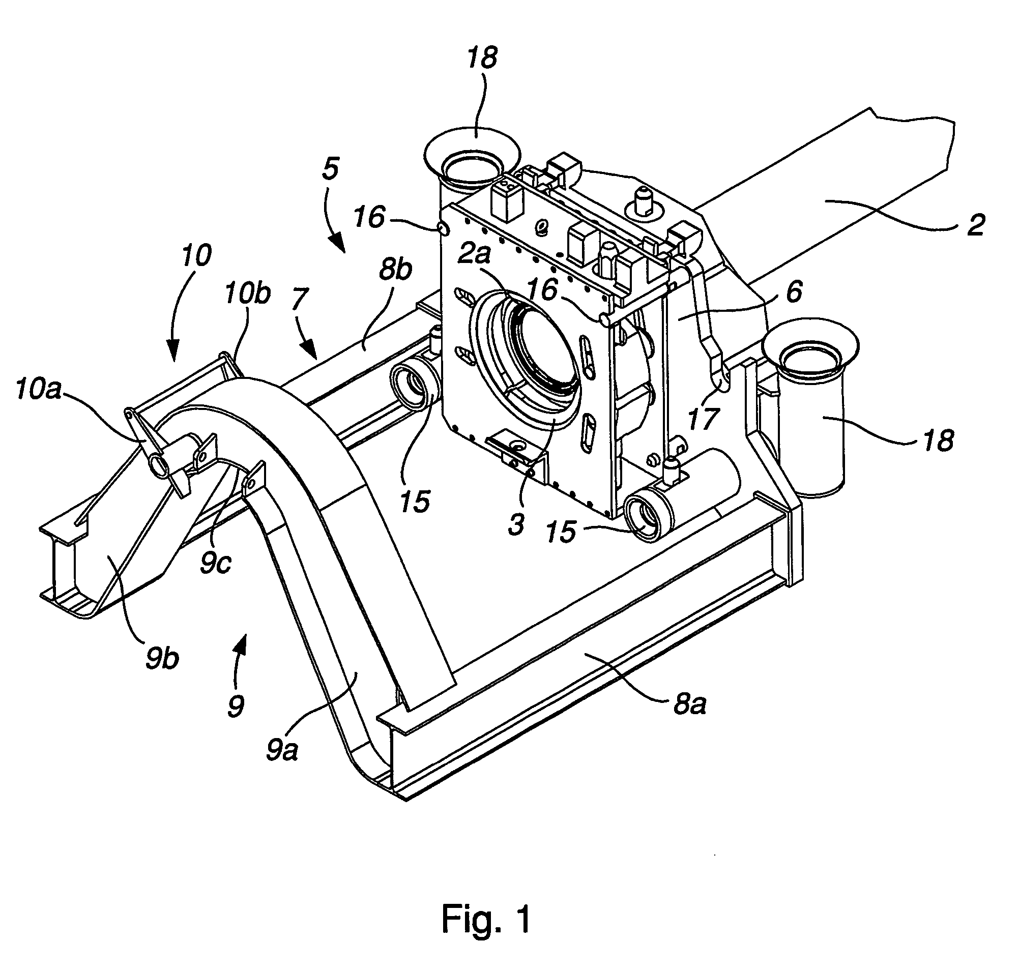
[0007] The spool piece termination structure according to the invention comprises a base frame, which is openly shaped downwards so as to allow the termination structure to receive a pipeline end section provided with a pipeline hub by lowering the termination structure downwards onto said pipeline end section. After the receipt of the pipeline end section in the termination structure, the actual connection of the pipeline hub to the spool piece hub may be performed by displacing the pipeline hub and the spool piece hub with the clamping device in relation to each other so as to bring the pipeline hub and the spool piece hub into contact with each other, whereupon the clamping device is activated so as to clamp together the pipeline hub and the spool piece hub. Consequently, the initial connection between the pipeline hub and the spool piece termination structure is accomplished by lowering the termination structure downwards onto the pipeline hub. Thus, the entire pipeline may be laid on the seabed before the measures of connecting the pipeline to the spool piece are initiated. With the solution according to the invention, no landing platform or similar structure has to be secured to the pipeline end section when it is descended from the pipe-laying vessel, which will facilitate the pipe-laying operation and allow the pipeline to be laid out by means of a conventional pipe-laying vessel. Thus, the inventive solution will reduce the demands on the pipe-laying vessel with respect to its equipment as compared to the prior art solutions where a landing platform or the similar is secured to the pipeline before it leaves the pipe-laying vessel.
[0008] According to a preferred embodiment of the connection arrangement according to the invention, the alignment structure is designed to receive at least a part of a rotationally symmetric flange of a pipeline end section. Hereby, the alignment structure may receive the pipeline end section flange irrespective of the roll angle of the pipeline end section and the associated pipeline hub. Consequently, the roll angle of the pipeline end section and the associated pipeline hub is of no importance during the installation of the pipeline on the seabed and during the subsequent operations for connecting the pipeline hub to the spool piece hub. Thus, the pipeline end section and the associated pipeline hub may be laid on the seabed with arbitrary roll angle, which will facilitate the pipe-laying operation.
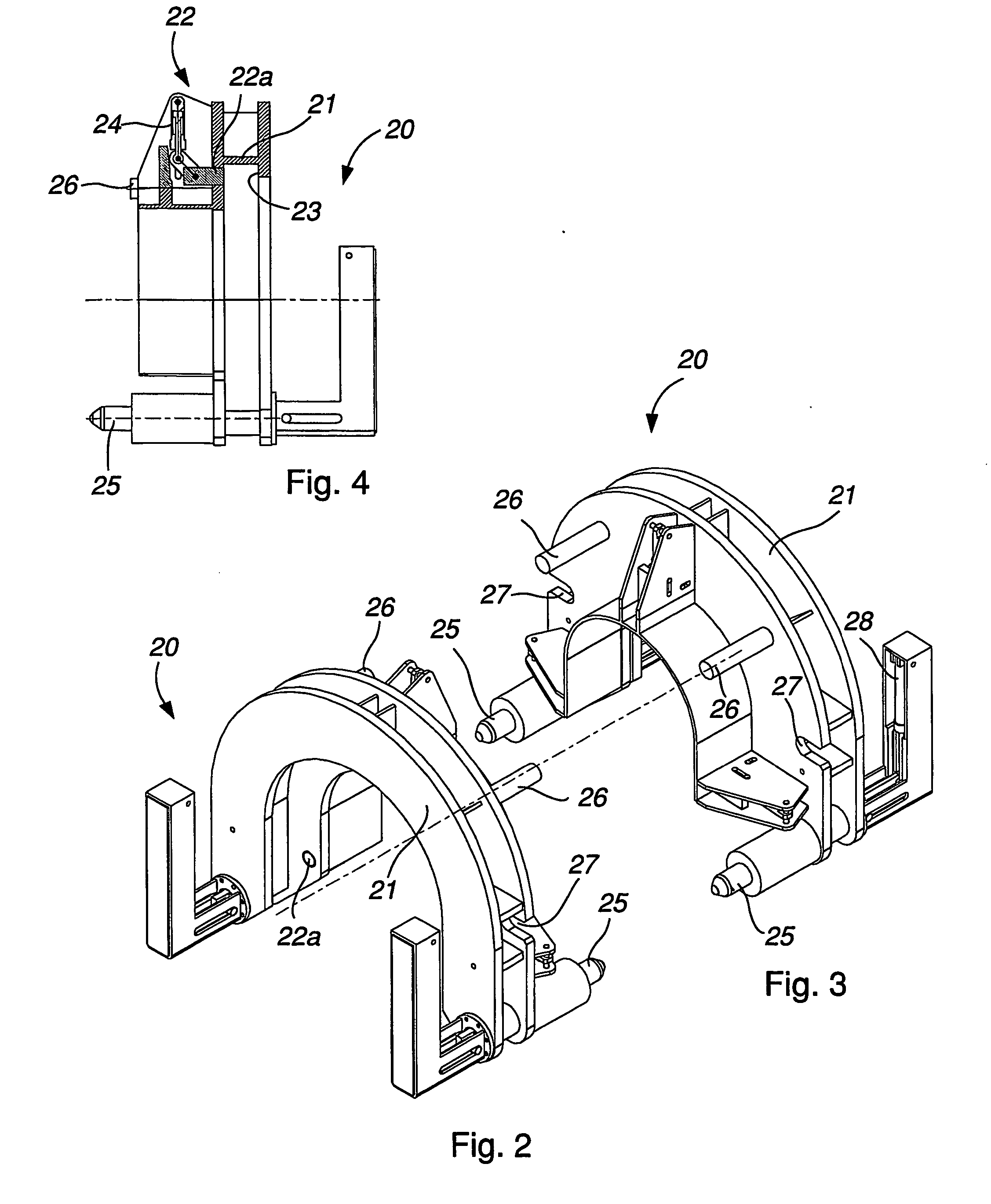
[0010] According to another preferred embodiment of the connection arrangement according to the invention, one of the alignment structure and termination structure is provided with at least one male-like alignment member, preferably in the form of a spear, which is designed to fit into a corresponding female-like alignment member, preferably in the form of a spear funnel, arranged on the other of said structures. This will provide a co-axial alignment so as to allow the mutual alignment shoulder / recess arrangement of the hubs perform the final alignment and load transfer. The respective male-like alignment member is preferably displaceably mounted in the associated structure so as to allow the alignment member to be retracted out of the corresponding female-like alignment member without having to displace the entire alignment structure in relation to the termination structure. This will facilitate the retrieval to the surface of the alignment structure after the completion of the connection between the pipeline hub and the spool piece hub.
[0012] The invention also relates to a pipeline termination having the features of claim 26. The design of the pipeline termination with a flange located behind the pipeline hub will allow the pipeline termination to be manipulated sub-sea during the operations for connecting the pipeline hub to a corresponding spool piece hub, without requiring any complex and / or bulky equipment to be attached to the pipeline termination before it is descended into the sea from a surface vessel.
[0013] According to a preferred embodiment of the pipeline termination according to the invention, said flange is rotationally symmetric. Hereby, the roll angle of the pipeline termination is of no importance during the installation of the pipeline on the seabed and during the subsequent operations for connecting the pipeline hub to the spool piece hub. Thus, the pipeline termination may be laid on the seabed with arbitrary roll angle, which will facilitate the pipe-laying operation.

Problems solved by technology

Consequently, this known connection arrangement and method are not appropriate for use when connecting a spool piece to a pipeline that has previously been laid on the seabed.
This will raise the costs for the pipe-laying vessel and reduce the number of vessels available for the pipe-laying operation, which could cause high costs for performing the pipe-laying operation.

Method used


Image

  • Spool piece termination structure, a connection arrangement comprising such a termination structure and a pipeline termination
  • Spool piece termination structure, a connection arrangement comprising such a termination structure and a pipeline termination
  • Spool piece termination structure, a connection arrangement comprising such a termination structure and a pipeline termination

Examples


Embodiment Construction

[0023] A spool piece termination structure 5 according to a first embodiment of the present invention is shown in FIG. 1. The termination structure 5 is intended for use in subsea connection of a pipeline 1 (see FIGS. 5-7) to a spool piece 2 and comprises a clamping device 3 for clamping together a pipeline hub 1a (see FIGS. 5-7) secured to the end of the pipeline and a corresponding spool piece hub 2a secured to the end of the spool piece. The spool piece hub 2a and the associated spool piece 2 are to be mounted to the termination structure 5 before being lowered into the sea from a surface vessel. Thus, the spool piece hub and the spool piece are mounted to the termination structure before the performance of a connecting operation. In the illustrated embodiment, the clamping device 3 is attached to a vertical base plate 6 forming part of the body of the termination structure. The termination structure 5 comprises a base frame 7, which is openly shaped downwards so as to allow the ...


PUM

PropertyMeasurementUnit
Forceaaaaaaaaaa
Displacementaaaaaaaaaa
Symmetric field theoryaaaaaaaaaa

Abstract

A spool piece termination structure to be mounted to a spool piece so as to support a spool piece hub during the connection of the spool piece hub to a corresponding pipeline hub. The termination structure includes a clamping device for clamping together the spool piece hub and pipeline hub, and a base frame openly shaped downwards so as to allow the termination structure to receive a pipeline end section provided with the pipeline hub by lowering the termination structure downwards onto the pipeline end section. A connection arrangement includes such a spool piece termination structure and a method for subsea connection of a pipeline to a spool piece.

Description

FIELD OF THE INVENTION AND PRIOR ART [0001] The present invention relates to spool piece termination structure according to the preamble of claim 1 and a connection arrangement for subsea connection of a pipeline to a spool piece comprising such a termination structure. The invention also relates to a method according to the preamble of claim 20 for subsea connection of a pipeline to a spool piece. The invention also relates to a pipeline termination according to the preamble of claim 26. [0002] Development within offshore oil and gas exploration in the recent years has been directed to subsea installations for processing and transport of oil and gas. These subsea installations replace the traditional platforms, where oil and gas was transported up to the platform for further processing and transport. This development of subsea production, processing and transport systems has resulted in an increasing need for subsea connection arrangements for coupling together a longer pipeline in...

Claims


Application Information

Patent Timeline
IPC IPC(8): F16L1/12E21B43/01
CPCE21B43/0107F16L1/12Y10S285/92Y10T29/53357F16L1/26
Inventor BASTESEN, ROLFINGEBRETSEN, HELGEWITTING, FREDRIK
Owner VETCO GRAY SCANDINAVIA
Learn More