
Device for extending bones

Inactive Publication Date: 2007-01-11
WITTENSTEIN GROUP
View PDF11 Cites 78 Cited by
  • Summary
  • Abstract
  • Description
  • Claims
  • Application Information

AI Technical Summary

Benefits of technology

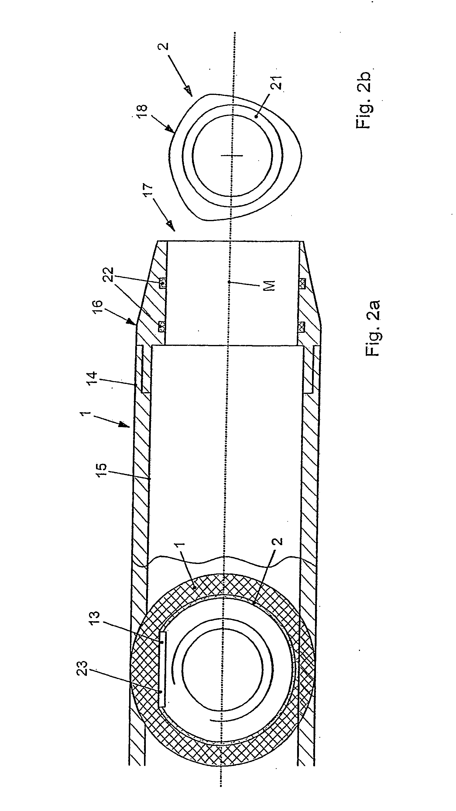
[0010] In the present invention, it has proven particularly advantageous that the second element is fitted into the first element in such a way that it is secured against radial torsion relative to said first element. The securing against torsion can be obtained in different ways. For example, an outer contour or outer cross section of the second element can have a polygonal configuration, while a correspondingly configured guide element with correspondingly configured inner cross section of the second element in the end area ensures securing against radial torsion. This makes it possible, inside the second element, to ensure a distraction, in particular an axial movement of the second element in relation to the first element, by means of a planetary roller system or thread or spindle system or the like, by way of the drive element. This distraction, as a function of the gear ratio of the planetary roller system, ensures very high distraction forces, while at the same time an exact distance or distraction can also be traveled per unit of time. In addition, the distraction or each travel can be exactly activated and executed.

Problems solved by technology

A disadvantage of conventional devices is that they do not have high distraction forces and are technically very complex and expensive to manufacture, and, in addition, are to be produced in a limited size.
For this reason, the possible applications are very limited, particularly in bones of short length and small diameter.
An additional disadvantage is that conventional distraction devices have a short travel and, after the complete travel has been exhausted, other distraction devices or appliances have to be fitted, which is also undesirable.

Method used


Image

  • Device for extending bones
  • Device for extending bones
  • Device for extending bones

Examples


Embodiment Construction

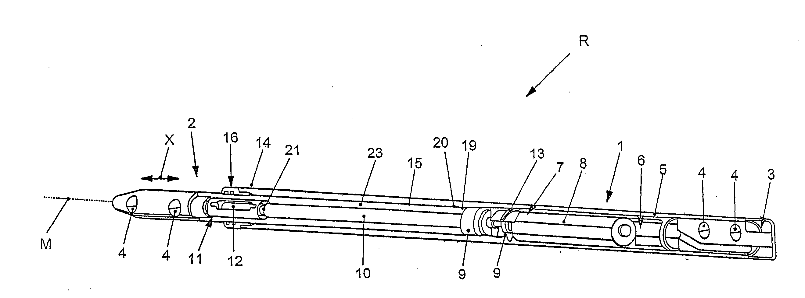
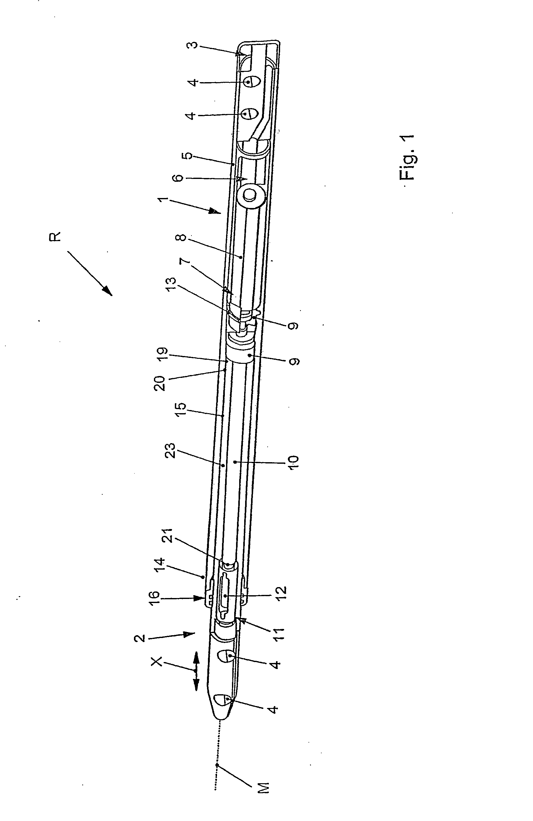
[0020] According to FIG. 1, a device R according to the invention comprises a first element 1, and a second element 2 that is guided linearly and axially in said first element 1.

[0021] Integrated in the first element 1, particularly in the end area, there is an energy and / or data transmission element 3 which delivers the required energy and ensures bidirectional and contactless exchange of data. In the end area 19 of the element 1, there are also at least two radial locking bores 4 which serve to fix the device R for example in a bone that is to be extended. At the same time the element 1 is secured against radial torsion relative to the bone during fixing.

[0022] The element 1 is preferably designed as a receiving sleeve 5 that comprises an electronics unit 6 (only symbolically indicated here) connected to the energy and / or data transmission element 3 and also to a drive element 7.

[0023] The drive element 7 comprises an electric motor 8 which sets a drive shaft 10 in a rotary mov...


PUM


Abstract

A device for extending bones, comprising two elements that can be displaced in relation to one another and that are interconnected by at least one drive element. When the two elements are displaced axially in relation to one another, they are guided in a manner that prevents relative radial torsion.

Description

BACKGROUND OF THE INVENTION [0001] The present invention relates to a device for extending bones, with two elements that can be moved in relation to one another and that are interconnected via at least one drive element. [0002] Devices of this kind are known and commonly available on the market in a wide variety of formats and designs. They are used in particular for distraction of bones. They can be inserted into a bone cavity or a medullary space of a bone, and distraction can take place after the bone has been cut through. [0003] A disadvantage of conventional devices is that they do not have high distraction forces and are technically very complex and expensive to manufacture, and, in addition, are to be produced in a limited size. For this reason, the possible applications are very limited, particularly in bones of short length and small diameter. [0004] An additional disadvantage is that conventional distraction devices have a short travel and, after the complete travel has be...

Claims


Application Information

Patent Timeline
IPC IPC(8): A61F2/30A61B17/00A61B17/72A61B19/00
CPCA61B17/7216A61B2019/464A61B2019/461A61B2017/00022A61B2090/064A61B2090/061
Inventor STAUCH, ROMAN
Owner WITTENSTEIN GROUP
Learn More