
Construction target indicator device

a technology of indicator device and construction target, which is applied in the direction of instruments, analogue processes, and specific applications using reradiation, can solve the problems of difficult operation and achieve the effect of more accurate and ready-to-use operation of work machines

Inactive Publication Date: 2007-01-11
KOMATSU LTD
View PDF5 Cites 89 Cited by
  • Summary
  • Abstract
  • Description
  • Claims
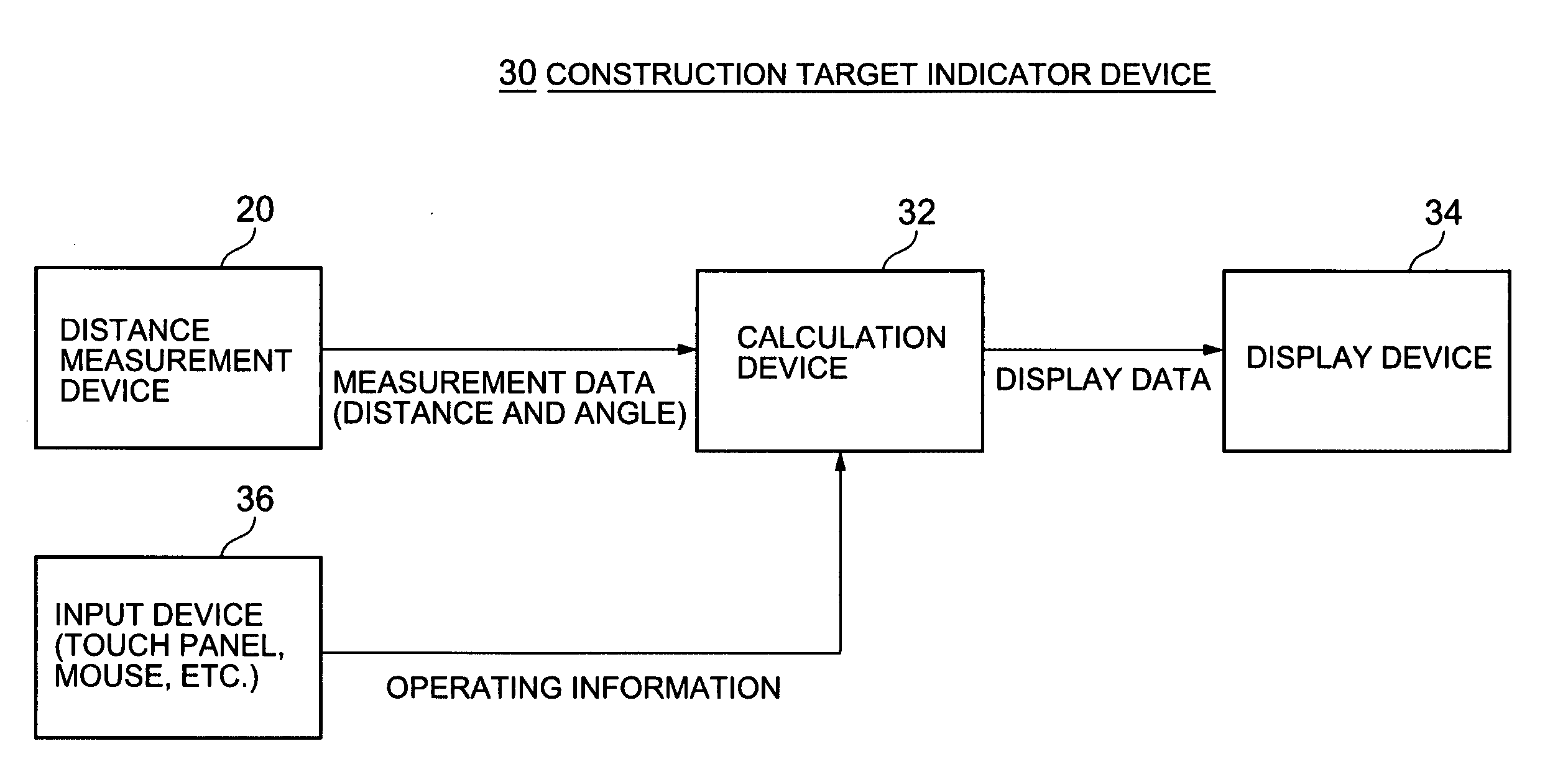
  • Application Information

AI Technical Summary

Benefits of technology

[0009] The object of the present invention is to provide a device whereby the shape of a construction surface and the position of a reference marker can be measured automatically, and information facilitating the operation of the work machine can be presented to the operator, by means of a simple composition.
[0010] The device for giving indications to the operator of a work machine according to the present invention comprises: a measurement device for measuring the position of a construction surface, which is a current work object, and the position of other objects located in the vicinity of construction surface, while the work machine is performing work; a reference point detection unit for detecting reference points corresponding to reference markers disposed in the vicinity of the construction surface, from the positions of the construction surface and the other objects measured by the measurement device; a virtual line calculation unit for calculating a virtual line corresponding to a target surface that is to be formed, on the basis of the reference points detected by the reference point detection unit; a display data creation unit for creating display data for displaying images indicating the positions of at least the construction surface and the virtual line, on the basis of the positions measured by the measurement device and the virtual line calculated by the virtual line calculation unit; and a display device (34) for receiving the display data from the display data creation unit and displaying the images on a display screen. Therefore, an image indicating the position of a construction surface, which is the current work object, and the position of a virtual line corresponding to a target surface that is to be formed, are displayed on the display screen. Since the operator of the work machine can tell the positional relationship between the construction surface and the target surface, from the displayed image, he or she is able readily to judge the extent of the machining that is to be applied to the construction surface by operating the work machine.
[0011] The position of the other objects in the vicinity of the construction surface which are detected by the measurement device may also be displayed, together with the construction surface and the virtual line. The other objects thus detected generally include, for example, reference markers which are disposed in the vicinity of the construction surface, an acting component which acts directly on the construction surface worked by the work machine (for example, an excavation bucket in the case of a hydraulic shovel), and the like. Since human beings have an extremely high capacity to recognize patterns, the operator can readily identify, by looking at the displayed image, which part of the display images corresponds to the acting component, which part corresponds to the construction surface, and which part corresponds to the virtual line, and hence he or she can readily judge how the work machine should be moved.
[0019] Furthermore, the position of the acting component thus detected may be corrected by means of a prescribed offset amount, and the corrected position of the acting component may be displayed together with the positions of the construction surface and the virtual line. In a preferred embodiment, the positions of the inner surfaces of an excavation bucket, which forms the acting component of a hydraulic shovel, are measured by means of a measurement device, these positions of the inner surfaces are corrected by means of an offset corresponding to the thickness of the excavation bucket, in such a manner that they correspond approximately to the positions of the outer surfaces of the excavation bucket, and the positions of the inner surfaces of the excavation bucket thus corrected are displayed together with the construction surface and the virtual line. Thereby, the operator is able to ascertain the position of the acting component, accurately.
[0020] A display showing an enlarged, or emphasized, view of the positional error between the construction surface and the virtual line may also be shown in response to a request from the operator. Accordingly, the operator can readily operate the work machine even more accurately.

Problems solved by technology

Therefore, the operation is not simple to carry out.

Method used


Image

  • Construction target indicator device
  • Construction target indicator device
  • Construction target indicator device

Examples


first embodiment

[0042]FIG. 3 is a perspective diagram showing an example of a situation where a sloped surface is being excavated by a construction machine, for example, a hydraulic shovel, which is equipped with a first embodiment of a construction target indicator device according to the present invention. In the near-side region of the work site illustrated in FIG. 3, excavation by means of the hydraulic shovel 1 has already been completed and a sloped surface 28 has been formed. In far-side region of the current work site, there exists, below the bucket 6, a construction surface 15 which is the object of the current excavation task. Reference markers (such as a plurality of posts 16, and a pair of cords 17 stretched between the cords 16, or the like, commonly known as “stakes”) have previously been disposed adjacently above the construction surface 15. The plane passing through these reference markers, and particularly, through the pair of cords 17, indicates the target sloped surface that is t...


PUM


Abstract

A construction target indicator device 30 presents information to the operator of a construction machine 1 in order to facilitate the operation thereof. In the construction target indicator device 30, a laser distance measurement device 20 disposed in the operator's cabin of the construction machine 1 automatically measures the real-time positions of a construction surface 15, reference markers 17 and a bucket 6. A calculation device 32 calculates the cross-sectional shapes of the construction surface 15 and the bucket 6, calculates a virtual line corresponding to a target sloped surface, and creates an image which depicts the cross-sectional shapes of a construction surface 15 and a bucket 6, and a virtual line. The display device 34 displays this image on the display screen. The operator is able to perform accurate excavation work by moving the bucket 6 in line with the virtual line on the display image.

Description

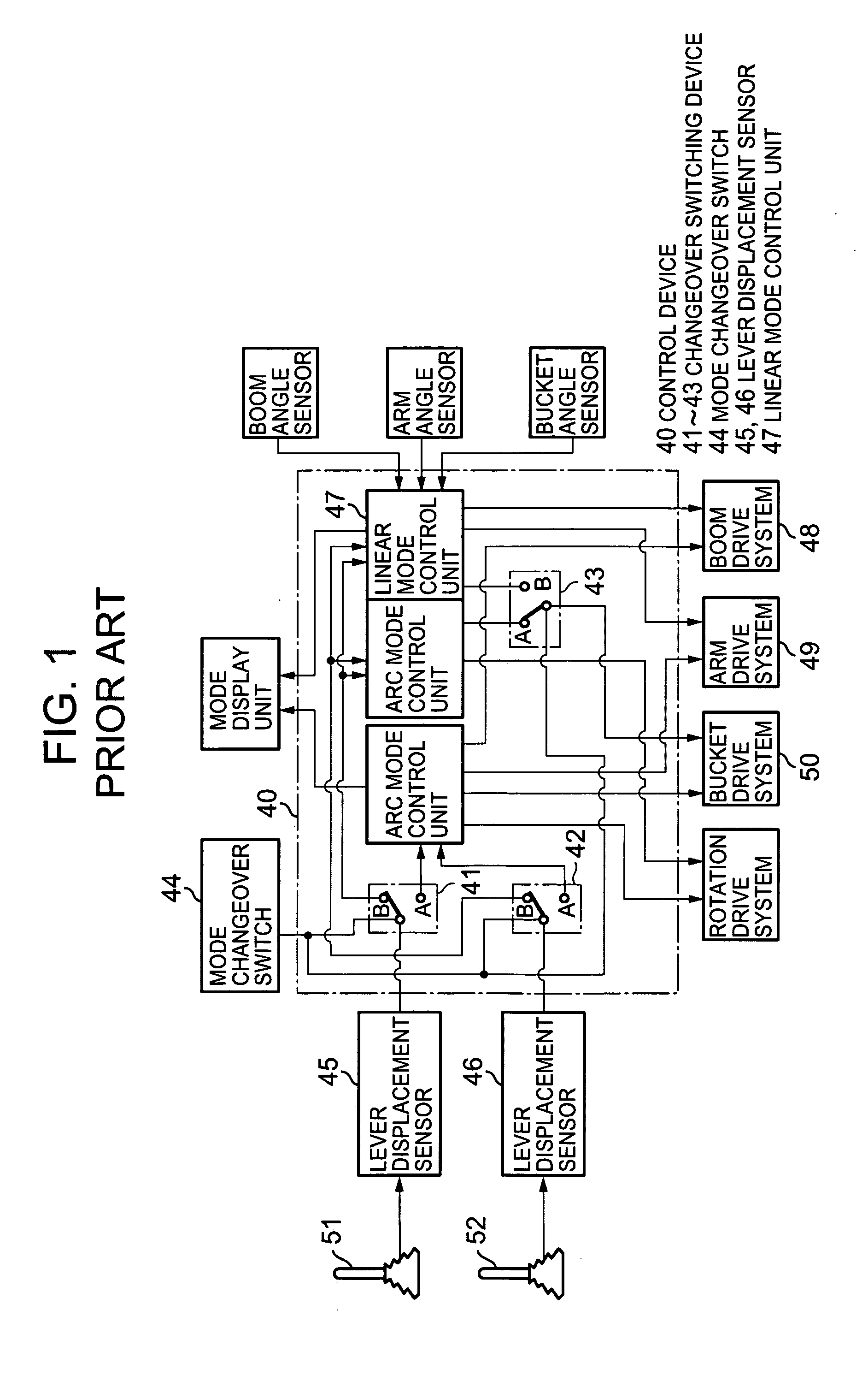
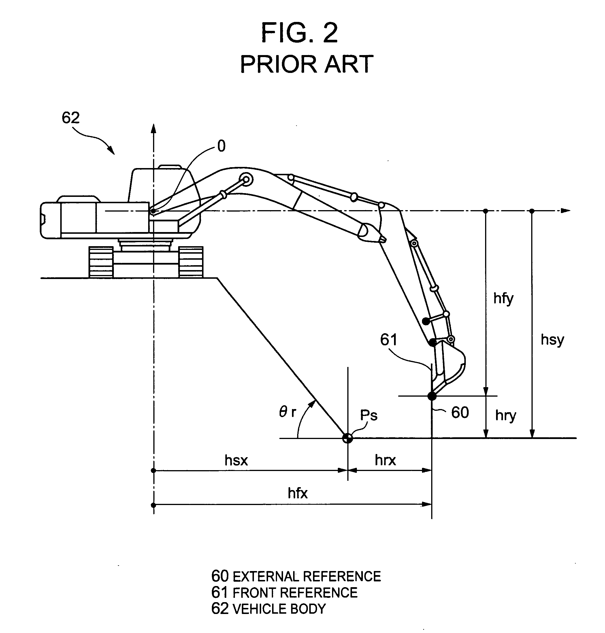
TECHNICAL FIELD [0001] The present invention relates to a construction target indicator device which can be used in the work of excavating a construction surface, and the like, performed by a work machine such as a hydraulic shovel, or the like. BACKGROUND ART [0002] Conventionally, for example, in a construction site, reference markers known as “finishing stakes” or “finishing guides” (in other words, a provisional device, such as a post, or a cord stretched between posts, which marks a reference surface or line) are provided in order to indicate the location at which excavation work is to be performed, to a work machine, such as a hydraulic shovel. The work machine is adjusted in the vertical direction by aligning the base or the blade tip of the bucket section of the hydraulic shovel with the reference marker. However, in a conventional construction method, as the bucket moves away from the reference marker, the target becomes more difficult to perceive and positional shifting fr...

Claims


Application Information

Patent Timeline
IPC IPC(8): G06F19/00E02F9/26G01C15/00
CPCE02F9/26E02F9/261E02F3/43G01S17/88
Inventor YOKOYAMA, YUKIKAGEYAMA, MASATOKAGEYAMA, MASATOMIYATA, KEISUKE
Owner KOMATSU LTD
Learn More