Method and Fixture for Assembling Supporting Disk of Motor Rotor

a technology of supporting disk and motor rotor, which is applied in the direction of manufacturing stator/rotor bodies, instruments, manufacturing tools, etc., can solve the problems of difficult to achieve the required bias and concentricity specifications by common processes, still have difficulties and limitations, and the precision requirements are very difficult to meet the current manufacturing process. , to achieve the effect of reducing cost, improving assembly precision and less precision

Inactive Publication Date: 2007-01-18
DELTA ELECTRONICS INC
View PDF9 Cites 0 Cited by
  • Summary
  • Abstract
  • Description
  • Claims
  • Application Information

AI Technical Summary

Benefits of technology

[0016] The object of the invention is to provide a method and fixture for assembling the supporting disk to a motor rotor. Departing from conventional thinking, the invention uses a method of “adjusting, and fixing” for assembling the supporting disk and the rotor. The method requires components of less precision that can reduce the cost while improve the assembly precision of less bias and higher concentricity.
[0017] An assembly method and fixture for assembling a supporting disk of a motor rotor according to the invention is based on an “adjusting, and fixing” concept. A functional axis fixture and an adjusting axis fixture, which can be engaged with each other for holding the supporting disk and the rotor, are first prepared. By engaging the functional axis fixture and the adjusting axis fixture, the functional axis of the supporting disk is aligned with the gometric axis of the rotor. Then, a stable and less influence method is used to fix the supporting disk and the rotor so that the bias and concentricity is improved through the precision controls of the fixtures.
[0018] The functional axis fixture in the invention is used to get the functional axis of the supporting disk. The functional axis means a specific working axis of the object carried by the supporting disk. Taking an optical disk for example, the functional axis is the geometric axis of the optical disk. The adjusting axis fixture in the invention is used to hold the rotor, and to engage with the functional axis fixture. When engaging the adjusting axis fixture and the functional axis fixture, the rotor and the supporting disk are aligned accordingly. By adjusting the functional axis fixture and the adjusting axis fixture, and fixing the supporting disk and the rotor, the precision of the assembly is effectively controlled.
[0019] The functional axis fixture is formed with a cavity for holding a supporting disk, and a plate having a same dimension of center hole of an optical disk for getting the functional axis after assembling the supporting disk. The adjusting axis fixture is formed with a cavity for holding the rotor. An axis of the adjusting axis fixture is pre-adjusted and aligned with the center hole axis of the plate of functional axis fixture. So, after engaging the two fixtures, the functional axis of the supporting disk is aligned with the axis of the rotor. Then, using a stable and less influence method to fix the rotor and the supporting disk, the bias and concentricity of the rotor and the supporting disk is therefore controlled and improved.

Problems solved by technology

However, such precision requirements are very difficult for the current manufacturing process. FIGS. 1A and 1B illustrate a conventional spin motor and the method of measuring axial bias and radial concentricity.
However, they still have difficulties and limitations as described below.
However, it is rather difficult to achieve the required bias and concentricity specifications by common process.
The parameters of injection molding process, such as temperature, flow passage, thermal shrinkage and precision of mold, are complicated to control.
The 0.015 mm bias requirement that depends on excellent molding and manufacturing techniques is further difficult to obtain.
It is not easy to achieve for rubber or silicone moldings that require specific molding and manufacturing attendance.
The aforesaid reasons make the component precision control difficult and expensive.
However, the post machining only improves the bias but does not help the concentricity.
Further, the machining generates dusts that may cause trouble to the assembly.
The furnishing of anti-glide material is less reliable because it cannot produce surface patterns that are preferred for a higher reliability.

Method used


Image

  • Method and Fixture for Assembling Supporting Disk of Motor Rotor
  • Method and Fixture for Assembling Supporting Disk of Motor Rotor
  • Method and Fixture for Assembling Supporting Disk of Motor Rotor

Examples


Embodiment Construction

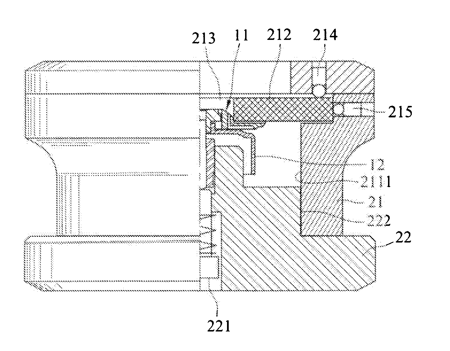
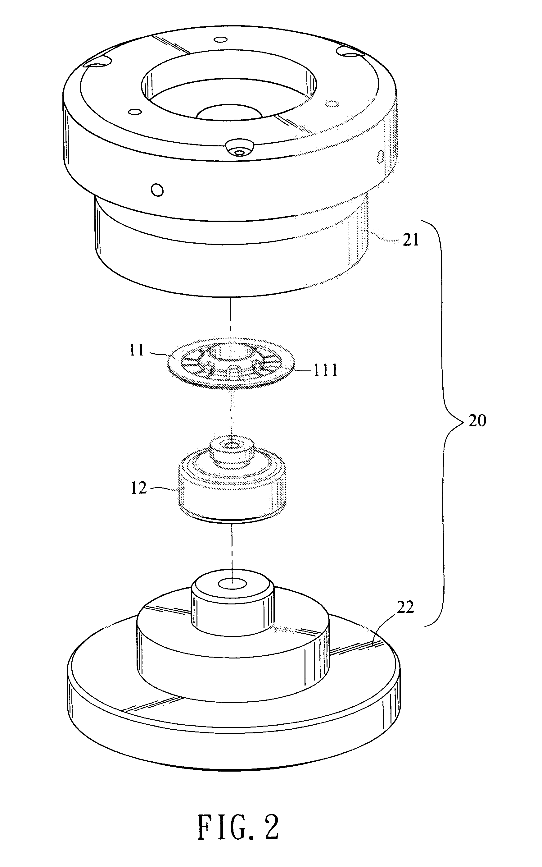
[0030] An assembly method and fixture for assembling a supporting disk of a motor rotor according to the invention is based or an “adjusting and fixing,” concept. A functional axis fixture and an adjusting axis fixture, which can be engaged with each other for holding the supporting disk and the rotor, are first prepared. By engaging the functional axis fixture and the adjusting axis fixture, the functional axis of the supporting disk is aligned with the geometric axis of the rotor. The fixtures can solve the functional axis problems of columnar variance, vibration, angular shift, angular velocity, tangent velocity, acceleration and so on.

[0031] The invention works on a supporting disk having a functional axis and a motor rotor having a rotation axis. A gap is preset between the supporting disk and the rotor for adjusting the relative position of the two. A set of fixture is provided for adjusting the distance and angle of the functional axis of supporting disk and the rotation axi...


PUM

PropertyMeasurementUnit
thickness parallelity toleranceaaaaaaaaaa
angleaaaaaaaaaa
heightaaaaaaaaaa

Abstract

An assembly method and fixture for assembling a supporting disk of a motor rotor according to the invention is based on an “adjusting, and fixing” concept. A functional axis fixture and an adjusting axis fixture, which can match with each other for holding the supporting disk and the rotor, are first prepared. The functional axis of the supporting disk is aligned with the geometric axis of the functional axis fixture, and the geometric axis of the rotor is aligned with the geometric axis of the adjusting axis fixture. By engaging the functional axis fixture and the adjusting axis fixture, the functional axis of the supporting disk is aligned with the geometric axis of the rotor. Therefore, the bias and concentricity can be precisely controlled and improved.

Description

CROSS-REFERENCES TO RELATED APPLICATIONS [0001] This application is a Divisional of co-pending application Ser. No. 10 / 427,905, filed on May 2, 2003, the entire contents of which are hereby incorporated by reference and for which priority is claimed under 35 U.S.C. § 120. This application also claims priority under 35 U.S.C. §119(a) on Patent Application No. 92101611 filed in Taiwan on Jan. 24, 2003, the entire contents of which are hereby incorporated by reference.BACKGROUND OF THE INVENTION [0002] 1. Field of the Invention [0003] The invention generally relates to a method and fixture for assembling supporting disk to a motor rotor, which is applicable to spindle motor for optical disk; and particularly relates to a method and fixture for assembling supporting disk to a motor rotor, through which the bias and concentricity arc is improved at one time. [0004] 2. Related Art [0005] Accompanying with technical developments of mass data storage with optical disks, the precision requir...

Claims


Application Information

Patent Timeline
Patent Type & Authority Applications(United States)
IPC IPC(8): H02K15/00H02K15/02B23P19/00G11B17/028G11B19/20H02K7/14H02K15/16
CPCB23P19/10G11B17/028G11B19/2009H02K7/14H02K15/00Y10T29/53265Y10T29/53143Y10T29/53261Y10T29/49009Y10T29/49012Y10T29/49682Y10T29/49025
Inventor YEH, DUNG-CHANGLIN, YUNG-PING
Owner DELTA ELECTRONICS INC
Why Eureka
Try Eureka