
Coupling device for a motor vehicle fluid circuit

a fluid circuit and coupling device technology, applied in the direction of liquid fuel feeders, pipe elements, corrosion prevention, etc., can solve the problems of increasing the risk of the vehicle catching fire, questioning the possibility of making such couplings by machining, and not being able to achieve sharp angles, so as to achieve the effect of convenient connection

Active Publication Date: 2011-02-15
NORMA AUTOLINE FRANCE SAS +1
View PDF41 Cites 13 Cited by
  • Summary
  • Abstract
  • Description
  • Claims
  • Application Information

AI Technical Summary

Benefits of technology

[0008]The invention seeks to propose an alternative to fabricating metal couplings, which alternative combines the advantages of metal couplings to withstand impacts with the advantages of plastic material couplings in terms of compactness, and the shapes and sharp edges that make it easier to make connections.
[0010]This configuration imparts good strength to the protective shell of the invention. Nevertheless, the window is preferably provided by being cut out in a single shell so that the seam does not pass through any of the edges of the window. This increases ability to withstand impacts.
[0011]Amongst the advantages of the invention, mention can also be made of the fact that the shells, which do not contribute to the coupling function, can be dimensioned with less precision than is required for the bodies of metal couplings. As a result, fabrication is less expensive and does not excessively increase the total price of the coupling device.

Problems solved by technology

In the event of an accident, a rupture in this circuit considerably increases the risk of the vehicle catching fire.
However, for reasons of expense, it is out of the question to make such couplings by machining.
In addition, it is not possible to achieve sharp angles, such that connections by means of a spigot with sharp-edge peripheral portions in relief can be replaced only by a spigot with beads or bands in relief that require an external clamping collar.
It follows that a metal coupling produced using fabrication methods that are compatible with the market, i.e. by sheet metal working, present drawbacks compared with a coupling made of a plastic material, in particular in terms of overall size.

Method used


Image

  • Coupling device for a motor vehicle fluid circuit
  • Coupling device for a motor vehicle fluid circuit
  • Coupling device for a motor vehicle fluid circuit

Examples


Embodiment Construction

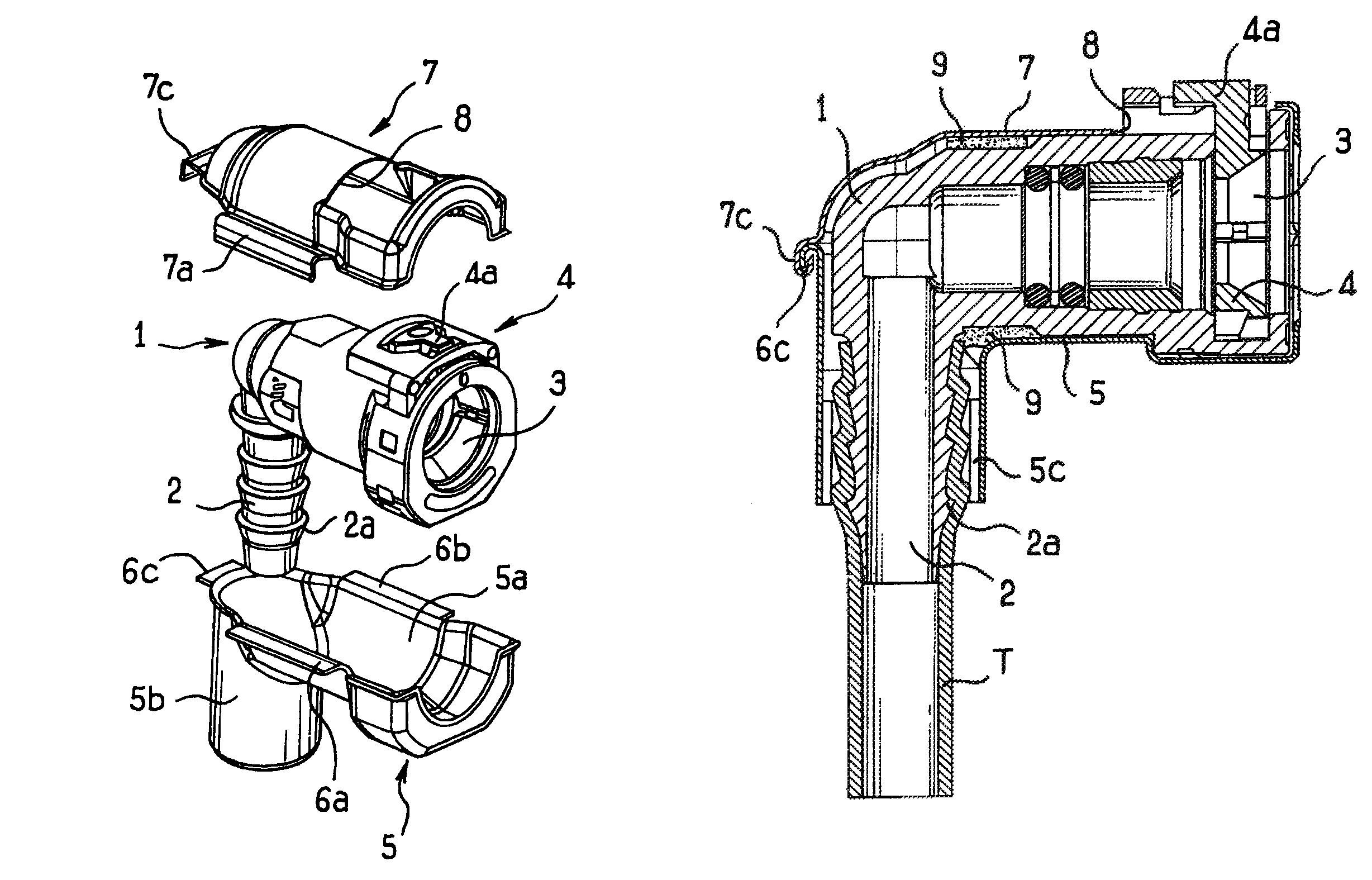
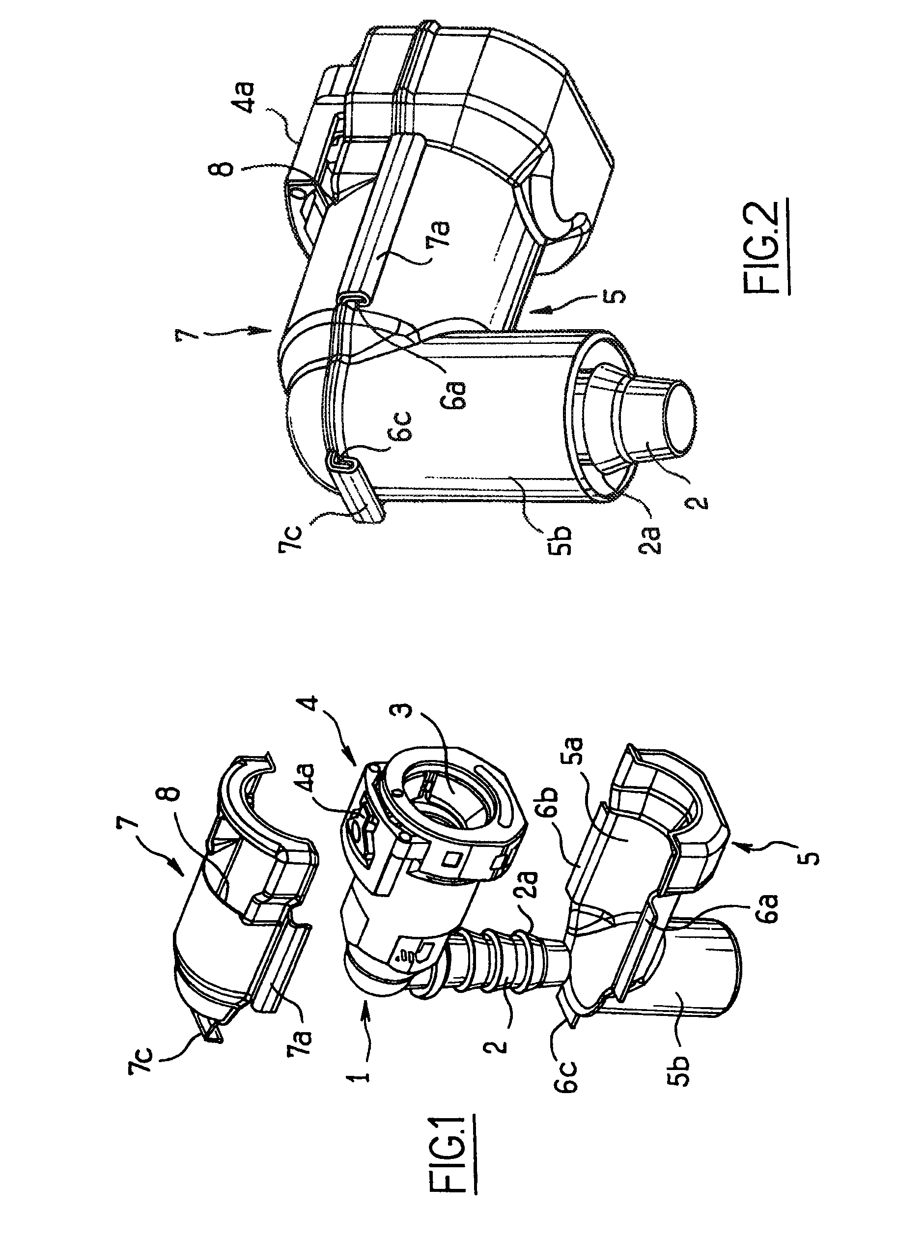
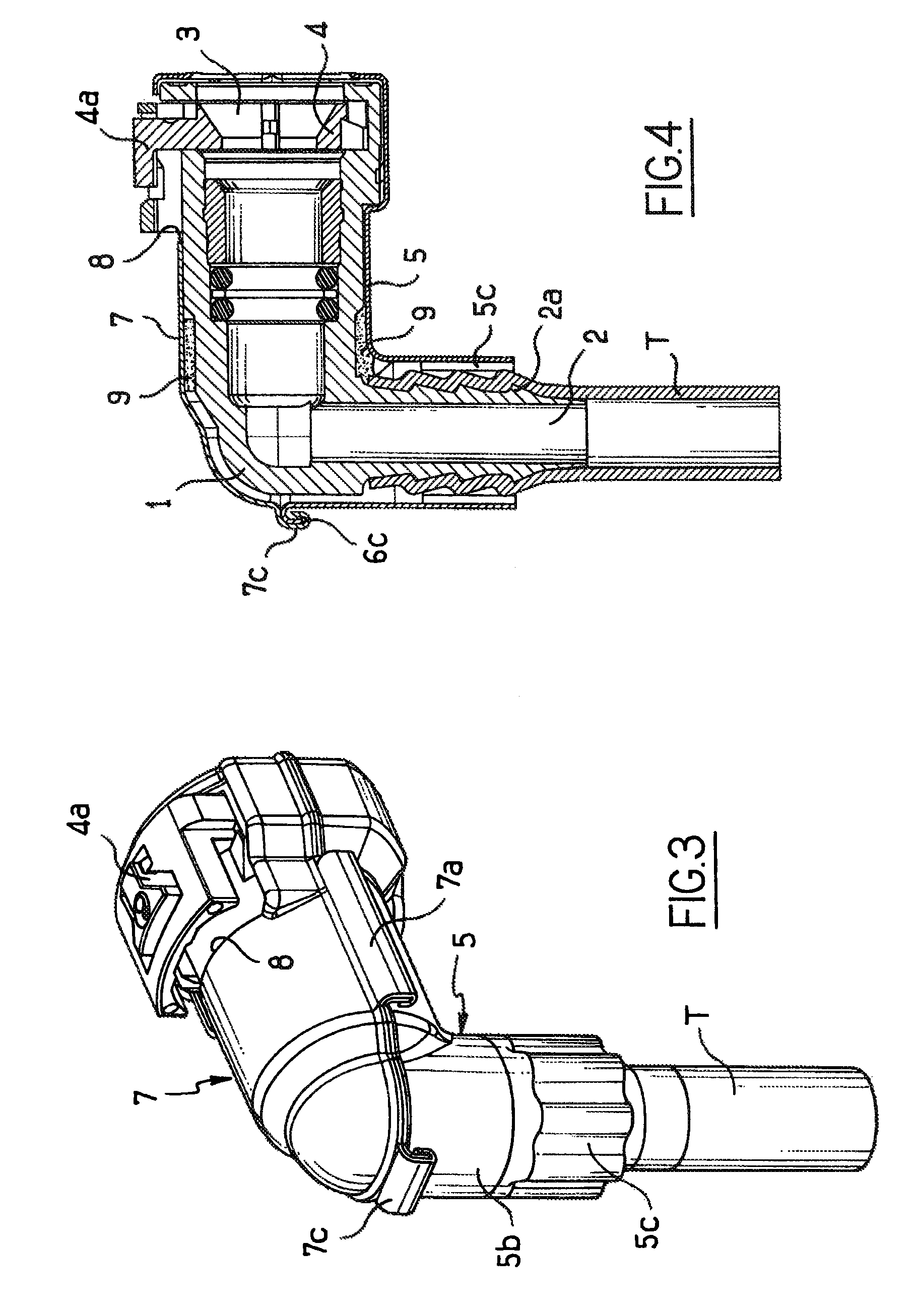
[0021]In the figures, the coupling device shown comprises a body 1 of plastic material, here of angled shape, having an internal channel and two different connection means, one formed by a serrated spigot 2 and the other formed by a housing 3 capable of receiving a collared end fitting, the housing being provided with a latch 4 and with drive means 4a projecting from the outside surface of the body 1. This body 1 fitted as described above constitutes a conventional plastic material coupling commonly used for making hydraulic circuits.

[0022]When the coupling is to be used in the field of conveying a dangerous or polluting fluid in a motor vehicle, the coupling is provided with a kind of metal armor in the form of box made up of two shells 5 and 7. The shell 5 defines a cradle 5a, and perpendicularly to the axis of the cradle, a sleeve 5b where the cradle is suitable for receiving the bottom portion of the main body 1, and the sleeve is suitable for receiving the spigot 2. A shell 7, ...


PUM


Abstract

Coupling device for a fluid circuit in a motor vehicle, the device including: a functional member of a plastic material that is provided with two or more types of connection, at least one of which includes a manually-accessible member projecting from the outside surface of the functional member; and a protective metal housing formed by two shells joined by a seam around the functional member, the housing being provided with a window giving access to the manually-accessible member.

Description

CROSS REFERENCE TO RELATED CASES[0001]This application is continuation of copending international Application No. PCT / FR07 / 001679 filed Oct. 15, 2007, which designated the United States, and which claims priority to French Patent Application 0609211, filed Oct. 20, 2006, the disclosure of each of which is expressly incorporated herein by reference.BACKGROUND OF THE INVENTION[0002]The present invention relates to a coupling device for coupling the various pipes forming a fluid circuit in a motor vehicle to one another or to other elements (filters, pumps, tanks).[0003]The fuel circuit of a motor vehicle is an element to which motor manufacturers devote a large amount of attention in terms of safety. In the event of an accident, a rupture in this circuit considerably increases the risk of the vehicle catching fire. It is therefore appropriate to provide circuits that can withstand the accident-simulating impacts to which these circuits are subjected during testing. This requirement al...

Claims


Application Information

Patent Timeline
Patent Type & Authority Patents(United States)
IPC IPC(8): F16L55/00F16L43/00F16L37/12F16L21/06
CPCF02M37/0017F16L58/18F16L37/0841F16L57/02
Inventor BLIVET, PHILIPPE
Owner NORMA AUTOLINE FRANCE SAS
Learn More