Dust separating apparatus

a technology of dust separation apparatus and dust collection part, which is applied in the direction of auxillary pretreatment, cleaning filter means, separation processes, etc., can solve the problems of reducing the capacity of dust separation apparatus, reducing so as to increase the capacity of dust collection part.

Inactive Publication Date: 2007-01-18
SAMSUNG GWANGJU ELECTRONICS CO LTD
View PDF2 Cites 70 Cited by
  • Summary
  • Abstract
  • Description
  • Claims
  • Application Information

AI Technical Summary

Benefits of technology

[0014] As described above, according to the dust separating apparatus consistent with embodiments of the present invention, the cyclone unit and the dust collection part are in arranged in parallel and the dust collection part is formed in a dead space surrounding the cyclone unit in the semicircular casing, thus

Problems solved by technology

Due to the cylindrical dust separating apparatus 30, a structural problem occurs: the creation of dead space S in the mounting chamber 13 can not be avoided.
Additionally, the contaminant receptacle 32 can not be manufactured over a c

Method used


Image

  • Dust separating apparatus
  • Dust separating apparatus
  • Dust separating apparatus

Examples


Embodiment Construction

[0022] Exemplary embodiments of the present invention will be described in detail with reference to the annexed drawings. In the drawings, the same elements are denoted by the same reference numerals throughout. In the following description, detailed descriptions of known functions and configurations incorporated herein have been omitted for conciseness and clarity.

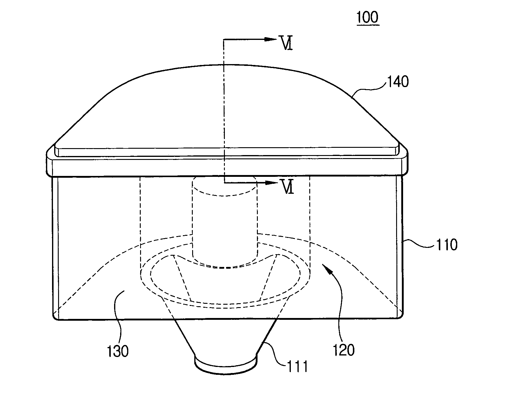
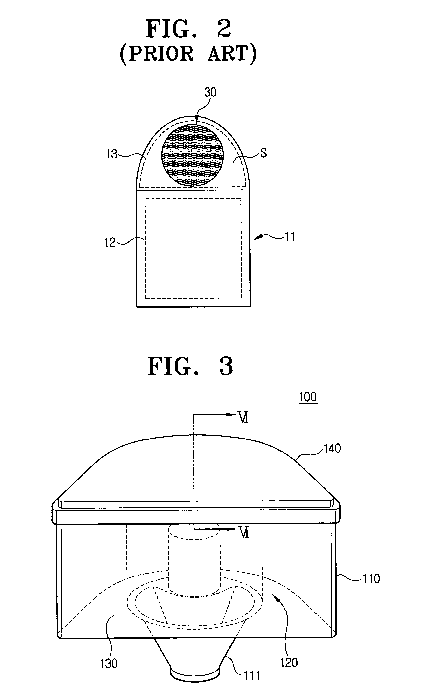
[0023] Referring to FIG. 3, a dust separating apparatus 100 of the present invention comprising a casing 110, a cyclone unit 120, a dust collection part 130, and a cover 140 is shown.

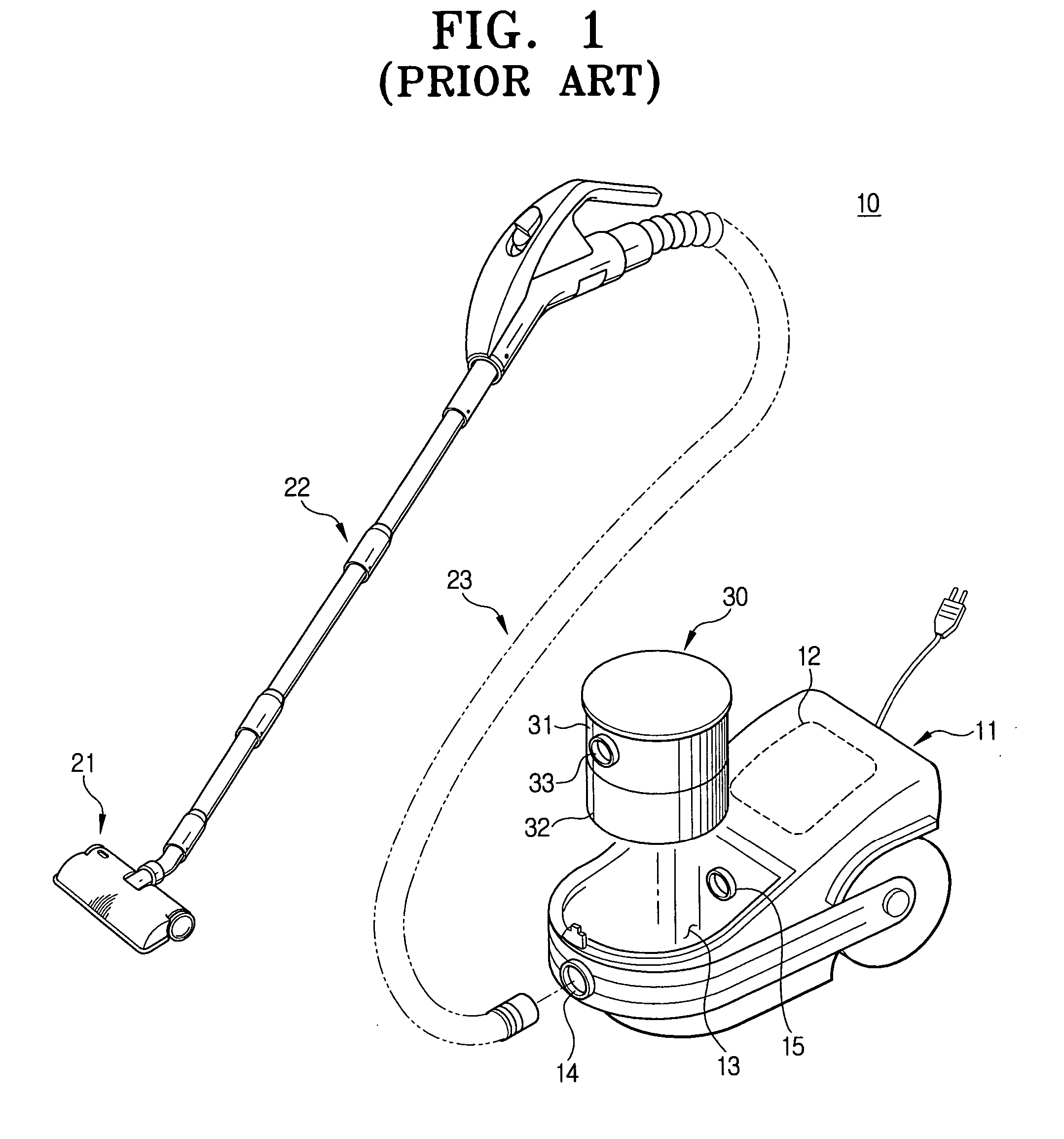
[0024] The casing 110 has a certain height and is substantially semicircular in cross section. In other words, the casing 110 is semicircular to correspond to the mounting chamber 13 (refer to FIG. 1) of the vacuum cleaner body 11, in which the dust separating apparatus 100 is mounted. The bottom surface of the casing 110 is connected with an inlet port 111 and an outlet port (not shown), the inlet port 111 is fluidly communicated with a su...


PUM

PropertyMeasurementUnit
Heightaaaaaaaaaa
Distanceaaaaaaaaaa

Abstract

A dust separating apparatus for a vacuum cleaner having a casing, a cyclone unit formed in the casing to filter contaminants from drawn-in air and discharge air removed of the contaminants, and a dust collection part arranged in parallel with the cyclone unit in the casing to collect the contaminant separated from the air by the cyclone unit. The casing is substantially semicircular to correspond to the mounting chamber of the vacuum cleaner body. On a bottom surface of the cyclone unit, an air inlet and an air outlet are formed. The air outlet is formed at one side of the air inlet.

Description

CROSS-REFERENCE TO RELATED APPLICATIONS [0001] This application claims the benefit under 35 U.S.C. §119 (a) of Korean Patent Application No. 2005-72796 filed on Aug. 9, 2005, the entire content of which is incorporated herein by reference. This application also claims the benefit of U.S. Provisional Application No. 60 / 698388 filed on Jul. 12, 2005, the entire content of which is also incorporated herein by reference.BACKGROUND OF THE INVENTION [0002] 1. Field of the Invention [0003] The present invention relates to a dust separating apparatus for a vacuum cleaner, which draws in contaminant-laden air from a cleaning surface, separates and collects contaminants from the air, and discharges clean air. [0004] 2. Description of the Related Art [0005] There are various kinds of dust separating apparatuses. Recently, a cyclone-type dust separating apparatus has been widely used, which is convenient and can be used semi-permanently, compared to a dust separating apparatus employing a tradi...

Claims


Application Information

Patent Timeline
IPC IPC(8): B01D45/18
CPCA47L9/1683Y10S55/03A47L9/10A47L9/16
Inventor OH, JANG-KEUNLEE, HAK-BONG
Owner SAMSUNG GWANGJU ELECTRONICS CO LTD
Why Eureka
Try Eureka