Drive systems and devices incorporating drive systems

Inactive Publication Date: 2007-01-18
AMEI TECH
View PDF18 Cites 17 Cited by
  • Summary
  • Abstract
  • Description
  • Claims
  • Application Information

AI Technical Summary

Benefits of technology

[0008] The direction in which the driven article is repositioned depends on whether the drive system is in the first or second position. Often, the drive element has two locking positions, oriented so that they are angularly displaced from each other by ninety degrees, and by switching between the two positions of the drive element, the driven article may be positioned along one axis without affecting the position of the driven article along the other axis. This allows for precise orientation of the driven article using the drive element, controlled by the single control element.
[0009] When the drive system is turned to the first position, rotation of the drive element causes the driven article to move in a first direction, while when the drive system is turned to the second position, rotation of the drive element causes the driven article to move in a second direction. And while an exemplary embodiment might have the first and second positions angularly displaced from each other by 90°, the axes could be positioned through a wide range of angles. Indeed, alternative embodiments may allow for a range of motion not simply along two axes, but through a wide range of angles, by allowing the drive element to interact with the driven article as it pivots throughout its angular range of motion.
[0010] In a typical embodiment, such a drive system might be used to control and fix the movement of two elements of a joint. This would provide a simple and effective means for a medical professional to calibrate various splint-like elements of a fixation device so that a patient's joint may be held in proper alignment. Using a single simple thumb wheel control element, the doctor would be able to position and calibrate the elements of a fixation device with great precision in one direction at a time (while the other direction was held securely in place). This sort of controlled rotational micromovement would assist medical professionals much more in setting the proper alignment than the free rotation provided by common ball-joint systems, by ensuring that only intentional actuation would take place.
[0012] In some embodiments, the position of the clamp assembly can be controlled by the control element so that the control element can simultaneously cause rotation of the first portion relative to the second portion and translation of the clamp assembly relative to the second portion. It may be especially useful to couple simultaneous translation in the longitudinal direction with rotation of the injured body part. Such an embodiment would allow for a single simple control element to provide precisely calibrated positioning of the fixation device (to stretch and support an injured body part in order to aid in healing), while also ensuring natural alignment of the bones by providing that the fixation device and the bones have a common point of origin of rotation.
[0013] The control element in such a fixation device may be moved between first and second positions. In the first position, the control element may be operable to rotate the first portion relative to the second portion in a generally horizontal plane. In the second position, the control element can be operable to rotate the first portion relative to the second portion in a generally vertical plane. Typically, an integrated locking mechanism also allows for rotation in only one direction at a time, and fixes the position of the drive element with respect to the driven article of the fixation device when switching between the two positions. This allows for precise calibration of the fixation device without the fear of introducing accidental movement. By using a drive system that incorporates the teachings of the present disclosure, rotation of the first portion in both the generally vertical and horizontal planes can be accomplished about a common point origin of rotation.

Problems solved by technology

Oftentimes, injury to a joint or bone can result in contracture, an abnormal tightening or shortening of the muscles and / or ligaments that may act to prevent a normal range of motion for the affected body part.
Treating contracture in joints can prove particularly problematic, since joints can undergo a wide range of motion.
Conventional fixation devices tend to introduce an unwanted compression to the joint socket or bone gap, since their point of origin for rotation is offset from that of the joint / bone.
This may introduce unwanted stress to the joint / bone that is the target of healing, slowing the healing process and possibly causing additional, unintentional injury.

Method used


Image

  • Drive systems and devices incorporating drive systems
  • Drive systems and devices incorporating drive systems
  • Drive systems and devices incorporating drive systems

Examples


Embodiment Construction

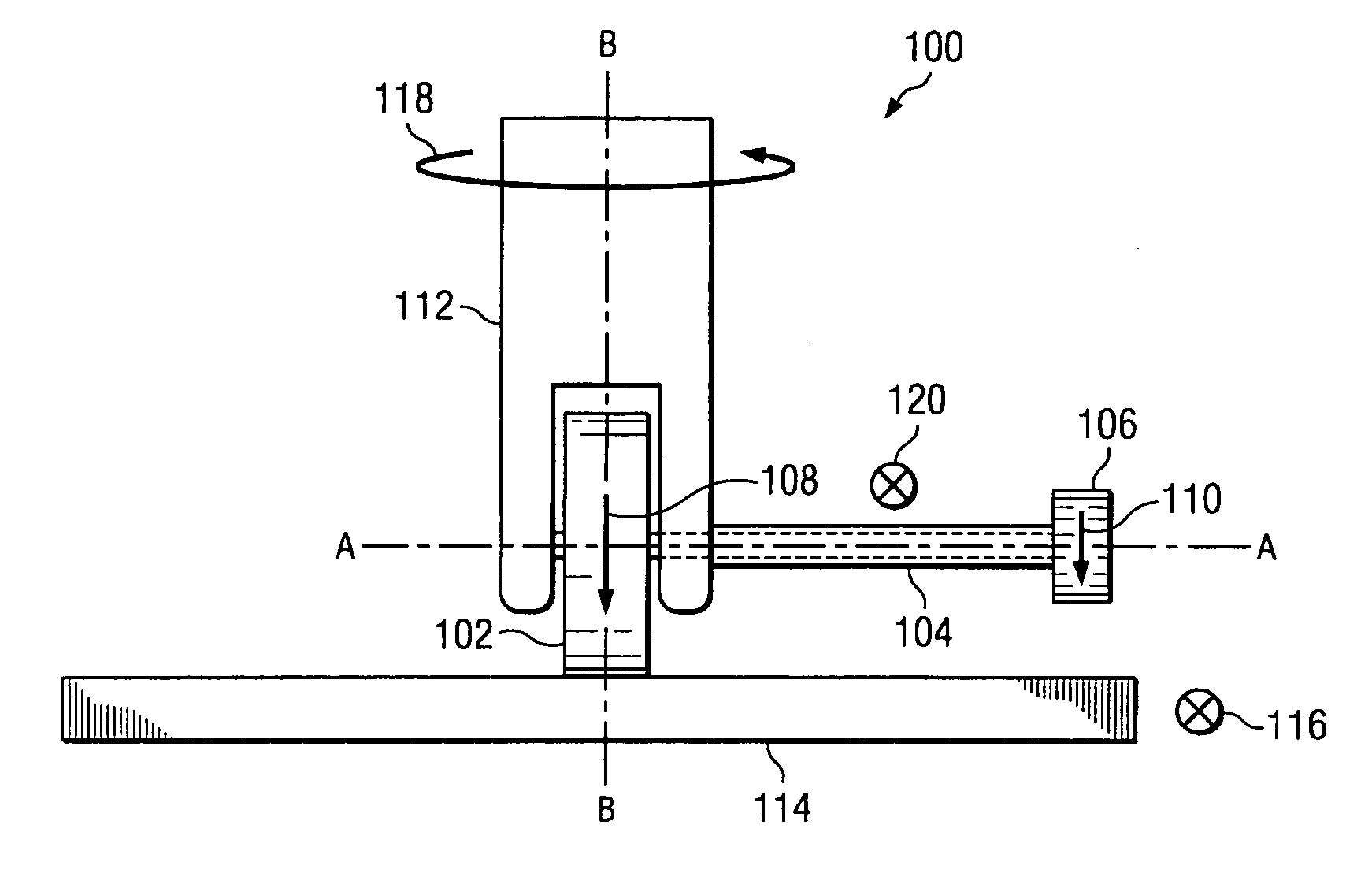
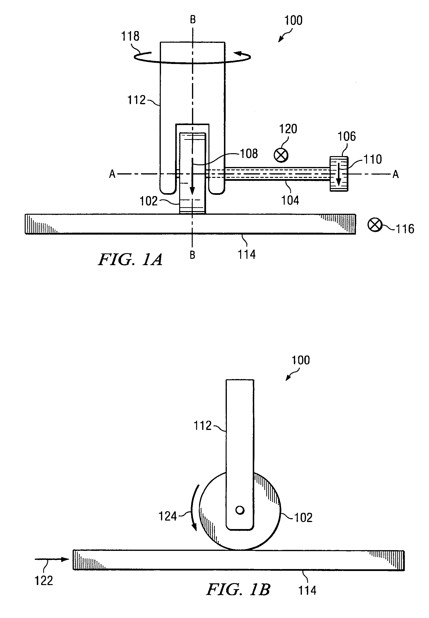
[0030]FIG. 1A shows an embodiment of a multi-directional drive system 100. The drive system 100 includes a drive wheel 102, which serves as a drive element, that can be driven to rotate by rotation of a thumb wheel 106, which serves as a control element. The thumb wheel 106 and the drive wheel 102 are connected by a drive shaft 104. The drive shaft 104 (shown in part with broken lines) extends along a longitudinal axis A-A and is fixed to the thumb wheel 106 such that it rotates about axis A-A as the thumb wheel 106 is rotated. The drive wheel 102 is fixed to the drive shaft 104 and rotates as the drive shaft 104 rotates. Thus, rotation of the drive wheel 102 can be controlled directly by rotation of the thumb wheel 106. For example, the drive wheel 102 can be rotated in the direction indicated by arrow 108 by rotating the thumb wheel in the direction indicated by arrow 110. Rotating the thumb wheel 106 in the opposite direction causes rotation of the drive wheel 102 in the opposite...


PUM


Abstract

Disclosed embodiments relate to a fixation device for use in supporting and / or stretching an injured body part. An exemplary disclosed fixation device uses a thumb wheel control element to provide controlled rotational micromovements of a joint. The control element and its associated drive system allow for movement along a particular axis, while the position remains fixed with relation to the other axis. In addition, the fixation device may incorporate a drive system that introduces a simultaneous longitudinal translation with rotation, in order to provide for a common point of origin of rotation between the fixation device and the affected body part supported by the fixation device.

Description

CROSS-REFERENCE TO RELATED APPLICATIONS [0001] This application claims the benefit of U.S. Provisional Application No. 60 / 674,052, filed on Apr. 22, 2005. U.S. Provisional Application No. 60 / 674,052 is commonly assigned with the present application and is hereby incorporated by reference for all purposes.FIELD OF THE INVENTION [0002] The disclosed embodiments relate generally to medical device technology, and more specifically to orthopedic fixation devices for treating contracture and to the drive systems that allows precise control for positioning and locking such fixation devices. BACKGROUND OF THE INVENTION [0003] Oftentimes, injury to a joint or bone can result in contracture, an abnormal tightening or shortening of the muscles and / or ligaments that may act to prevent a normal range of motion for the affected body part. Contracture may also be a congenital condition restricting motion. Treatment regimens for contracture typically involve the use of a fixation device, such as a ...

Claims


Application Information

Patent Timeline
IPC IPC(8): B60K1/00
CPCA61B17/68A61B17/6425
Inventor VASTA, PAUL J.
Owner AMEI TECH
Why Eureka
Try Eureka