Eureka AIR delivers breakthrough ideas for toughest innovation challenges, trusted by R&D personnel around the world.

Low voltage warming blanket

a low-voltage, electric blanket technology, applied in the direction of ohmic-resistance heating, heating element shapes, transportation and packaging, etc., can solve the problems of limited adoption and use of electric heating, general cost, and inability to provide heat to the occupant's legs or frontal regions, and achieve the effect of undue battery drain

Active Publication Date: 2007-01-18
DEVROY GARY
View PDF13 Cites 32 Cited by
  • Summary
  • Abstract
  • Description
  • Claims
  • Application Information

AI Technical Summary

Benefits of technology

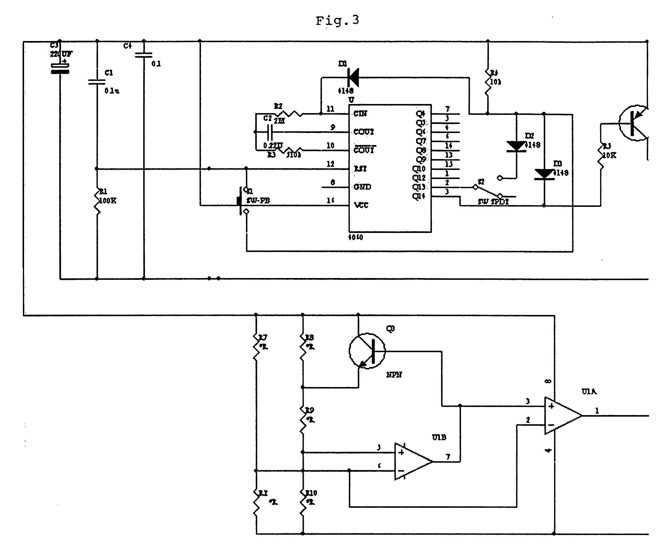
[0007] By use of a timing circuit, the device of this invention can be operated in a vehicle without fear of excessive battery discharge, irrespective of whether or not the power source socket is or is not associated with the ignition system or whether the ignition system is left in the accessories position. The use of the timing circuit also provides for use in a more convenient fashion in that a user, for example a driver anticipating having a passenger having the need for additional warmth, can activate the heating prior to the passenger's entry into the vehicle, irrespective of whether or not the engine is running, without fear that a delay in the arrival of the passenger will cause undue battery drain.

Problems solved by technology

While such heated seats in vehicles have proven utility in cold weather regions, they are generally expensive, not retrofittable into existing vehicles, and limited in that they provide heat only to the surface area of the seat itself and therefore generally do not provide heat to occupant's legs or frontal regions.
It has long been common to provide blankets, throws and other passive warming devices for use in vehicles, however the adoption and use of electric heating for such is limited for considerations of safety, versatility and battery overuse.
Electric utilizing devices plugged into such sockets, if left on after the engine and its associated generator or alternator have been turned off, can rapidly drain the vehicle's battery.
In those instances where the power socket, however, has been integrated into association with the ignition, power is not available when the ignition is off, although during such periods there may be a desire to power various electronic devices.
However, in the event of a relatively high drain power use device, such as would be provided by an electric warmer, long term use of such devices with the ignition in the accessory position can lead to excessive battery drain.

Method used


Image

  • Low voltage warming blanket
  • Low voltage warming blanket
  • Low voltage warming blanket

Examples


Embodiment Construction

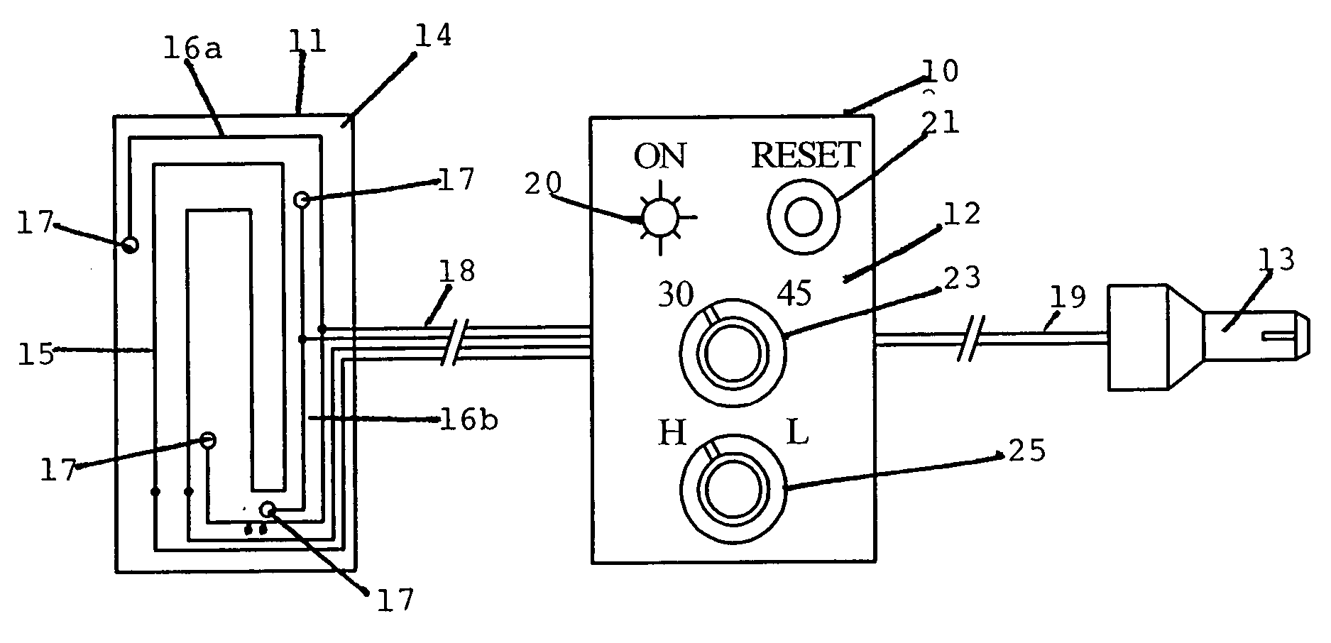
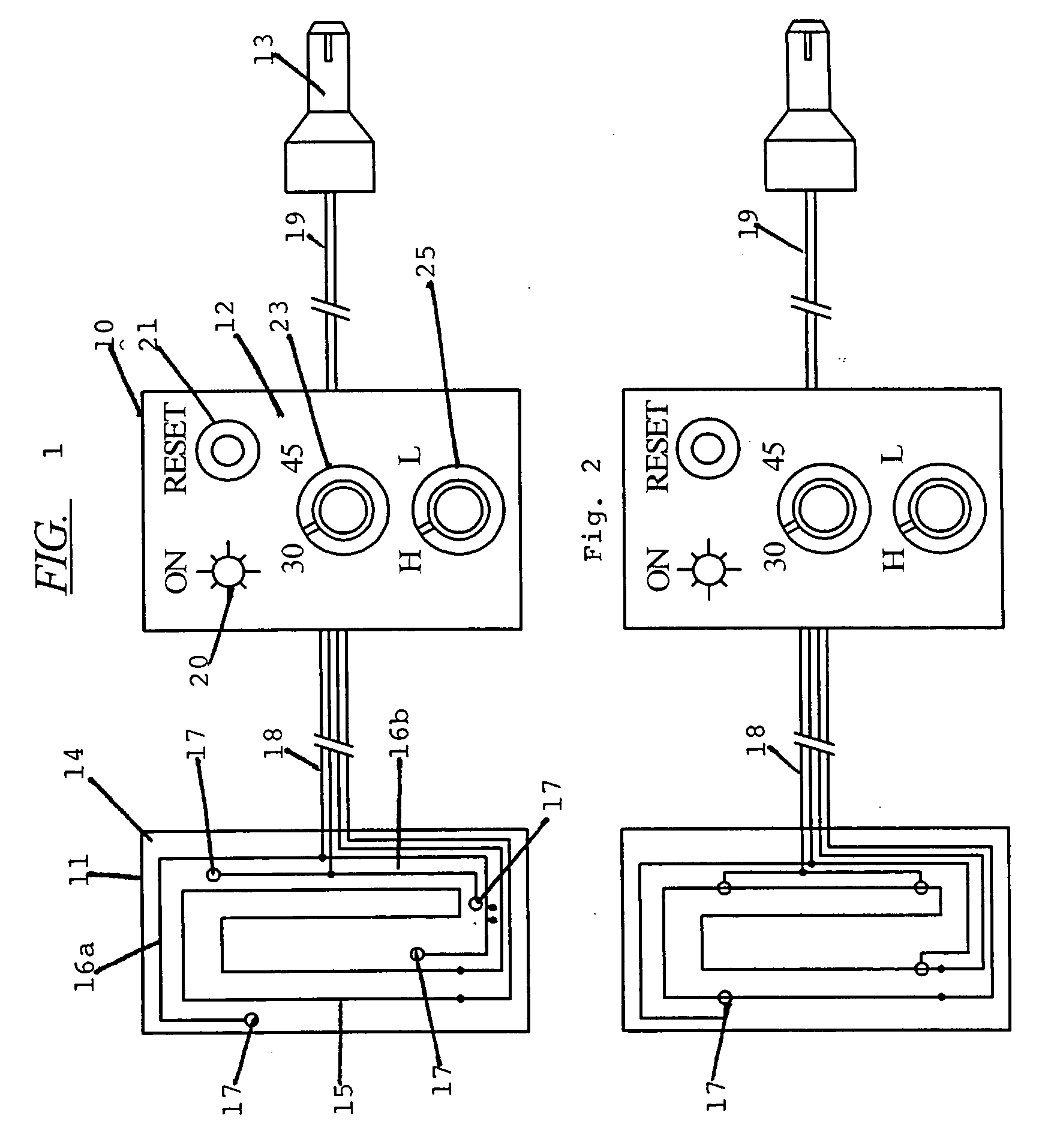
[0017] As shown in FIG. 1 the low voltage electric blanket device 10 of this invention is provided with a heated section 11, a control 12 and a plug 13. The plug 13 is preferably the type used with power sockets in vehicles which are connected to the vehicle DC low voltage system. As used herein, low voltage will be understood to mean that type of low voltage system generally used in vehicles, most commonly 12 or 24 volt, although in some systems higher voltages are known. Electric cords 18 and 19 connecting respectively the heated blanket area 11 to the control 12 and the control 12 to the plug are of a length to allow the blanket area to be positioned remote from the plug such as when the power socket is dash located and the user is in a rear seat while positioning the control near the user.

[0018] The heated area 11 consists of a blanket or throw 14 which is preferably formed of a fabric, either woven or non-woven and which may be bordered in any desired fashion or unboarded. Pre...


PUM


Abstract

A low voltage warming blanket adapted for use in vehicles powered by the vehicles DC power source is provided with a control selectively actuatable to activate the blanket for one of a plurality of preset time periods at at least one pre-set temperature, the control having a reset button to reinitiate activation upon expiration of the time period, the blanket being provided with thermal sensors preventing overheating.

Description

FIELD OF THE INVENTION [0001] This invention relates to electric blanket devices and more particularly to a low voltage electric blanket for automotive use incorporating preset timing periods. BACKGROUND OF THE INVENTION [0002] Electric heating pads, electric blankets, electric throws, and other localized fabric material heating devices are well known. Such devices commonly employ a heating area, generally in the form of a fabric member which is associated with one or more heating elements generally positioned interior of a multi-layer fabric member and safety and control circuitry which may include temperature setting selectively actuatable controls coupled to temperature sensors in the area of the elements. Such devices may be provided for different voltages. It has also been known to provide heated seats in automobiles and other vehicles where the heating coils are positioned under the seat surface and where the actuating controls include both on / off switches, temperature sensors...

Claims


Application Information

Patent Timeline
Patent Type & Authority Applications(United States)
IPC IPC(8): H05B1/00H05B3/00
CPCH05B3/342H05B2203/014H05B1/0227H05B2203/035H05B2203/029
Inventor DEVROY, GARY
Owner DEVROY GARY
Why Eureka
Eureka Blog
Learn More