Fundus camera

a camera and lens technology, applied in the field offundus cameras, can solve the problems of unstable frequent instability of the fixation of the eye, etc., and achieve the effect of improving the operability and not affecting the convenience of the function

Inactive Publication Date: 2007-01-18
NIDEK CO LTD
View PDF5 Cites 46 Cited by
  • Summary
  • Abstract
  • Description
  • Claims
  • Application Information

AI Technical Summary

Benefits of technology

[0007] An object of the invention is to over come the problems described above and to provide a fundus camera in which operability is improved while not impairing the convenience of the function of automatic alignment.

Problems solved by technology

Incidentally, in a fundus camera of non-mydriasis type utilizing natural mydriasis of the eye, fixation of the eye tends to be unstable since brightness of a fixation lamp for fixing a visual line of the examinee (the eye of the examinee) is suppressed to such an extent that a pupil of the eye does not contract.
However, the fixation of the eye frequently becomes unstable again also after the display switching from the anterior-segment image to the fundus image.

Method used


Image

  • Fundus camera
  • Fundus camera
  • Fundus camera

Examples


Embodiment Construction

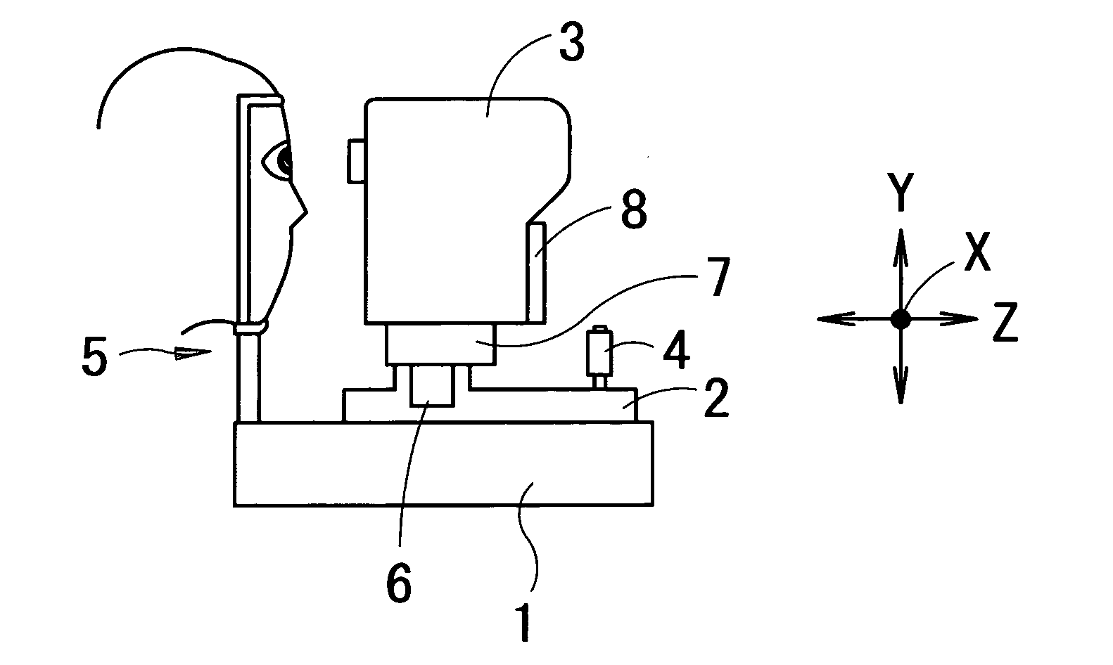
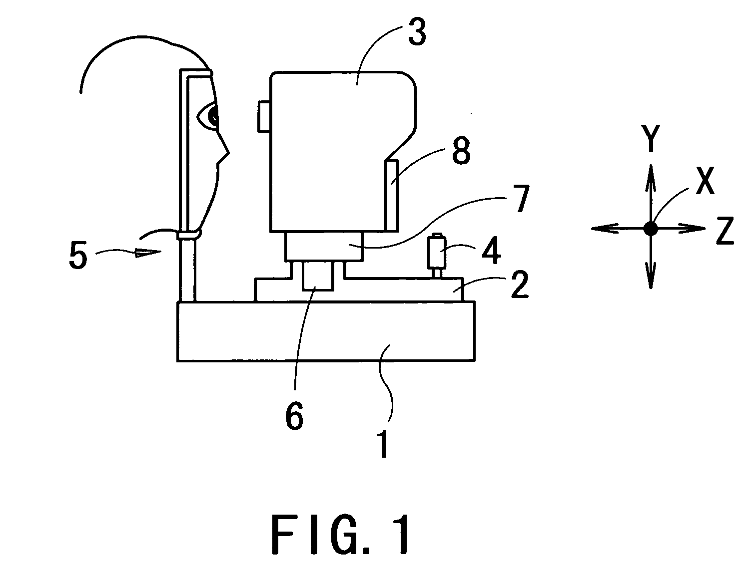
[0018] A detailed description of one preferred embodiment of a fundus camera embodied by the present invention is provided below with reference to the accompanying drawings. FIG. 1 is a view showing a schematic configuration of a fundus camera of non-mydriasis type consistent with the preferred embodiment of the present invention.

[0019] The fundus camera includes a base 1, a moving base 2 movable in a right-and-left direction (hereinafter referred to as an “X-direction”) and a back-and-forth direction (hereinafter referred to as a “Z-direction”) with reference to the base 1 through tilting operation of a joystick 4, a photographing part 3 movable in the right-and-left direction, an up-and-down direction (hereinafter referred to as a “Y-direction”) and the back-and-forth direction with reference to the moving base 2 under control of a control part 81 to be described later, and a face supporting unit 5 fixedly arranged on the base 1 for supporting a face (head) of an examinee. In an ...


PUM


Abstract

A fundus camera, in which operability is improved while not impairing the convenience of the function of automatic alignment, has a photographing part including a fundus photographing optical system, a moving unit which moves the photographing part, an observation optical system having a first image-pickup element which picks up a fundus image, an observation optical system having a second image-pickup element which picks up an anterior-segment image, a display unit capable of displaying the images, a control part which obtains information on alignment of the photographing part with the eye and controls driving of the moving unit based on the alignment information so that an alignment state satisfies a first reference condition, and a first input switch for inputting a signal for display switching from the fundus image to the anterior-segment image, wherein the control part prohibits the driving of the moving unit when the signal is inputted.

Description

BACKGROUND OF THE INVENTION [0001] 1. Field of the Invention [0002] The present invention relates to a fundus camera for photographing a fundus of an eye of an examinee. [0003] 2. Description of Related Art [0004] Conventionally, in fundus photographing using a fundus camera, rough alignment of a photographing part with an eye of an examinee is firstly performed while an image of an anterior-segment of the eye displayed on a monitor is observed, and then fine alignment of the photographing part with a fundus portion to be photographed is performed while an image of a fundus of the eye displayed on the monitor through display switching is observed. In recent years, a fundus camera having the function of automatically performing such alignment has been proposed (see Japanese Patent Application Unexamined Publication No. Hei8-275921 for example). [0005] Incidentally, in a fundus camera of non-mydriasis type utilizing natural mydriasis of the eye, fixation of the eye tends to be unstabl...

Claims


Application Information

Patent Timeline
Patent Type & Authority Applications(United States)
IPC IPC(8): A61B3/14
CPCA61B3/0041A61B3/145A61B3/12A61B3/152
Inventor ICHIKAWA, NAOKI
Owner NIDEK CO LTD
Why Eureka
Try Eureka