Apparatus and method for relay contact arc suppression

a technology of apparatus and relay, applied in the circuit field, can solve the problems of relay contact damage, relay contact damage, early failure of relay contacts, etc., and achieve the effects of reducing implementation costs, suppressing damaging arcing, and reducing costs for power supply users

Active Publication Date: 2007-01-18
WATLOW ELECTRIC MFG
View PDF56 Cites 37 Cited by
  • Summary
  • Abstract
  • Description
  • Claims
  • Application Information

AI Technical Summary

Benefits of technology

[0005] The inventors hereof have succeeded at designing a circuit for use in a power supply that suppresses damaging arcing across relay contacts providing output power while allowing for a cleaning arc across the relay contacts. The inventors hereof have recognized that arcing during the closing of the relay contacts provides a beneficial contact cleaning operation and that arcing during opening of the contacts is the harmful arcing that should be eliminated. As will be discussed and shown below, the various embodiments of the invention provide an improved apparatus and method for a power supply having a relay that has an extended relay life and therefore reduced costs for the power supply user. These benefits are provided in an optimal manner with only minimal incremental costs, but with significantly lower implementation costs than prior art systems and methods.
[0009] According to still another aspect, the invention is a method of suppressing damaging arcing across relay contacts in a power switch having a relay with a set of relay contacts providing a portion of input power to an output and a relay coil configured to control the set of relay contacts in response to receiving relay coil activating energy, and an auxiliary switch connected in parallel to the relay contacts and configured to provide supplemental load power to the output, the supplemental load power being a portion of the input power. The method includes receiving back EMF energy generated by the relay coil following termination of the relay coil receiving activating energy and connecting the supplemental load power to the output in parallel with the relay contacts in response to the receiving of the back EMF energy.

Problems solved by technology

Relays are used due to the low resistance and therefore power dissipation of the relay contacts as compared to alternative switching devices, such as solid state relays, that have significantly higher voltage drops across the closed switch.
However, the mechanical relays often degrade, at least in part, due to harmful arcing across the relay contacts that result from the relay contacts being powered before and after the opening and closing.
Such arcing can cause damage to the relay contacts such as pitting of the relay contacts and are the primary cause of relay breakdown.
This arcing is well known to cause early failure of the relay contacts and the need for replacement of the relays.
Typically, these electronic circuits have included complex and expensive solid state components that sense or detect the presence of arcing across the relay contacts and reduce the power at the relay contacts, thereby reducing the energy available for arcing.
Many of the attempts to eliminate arcing having attempted to suppress arcing at both the closing and opening of the relay contacts, as generally, heretofore, all contact arcing was considered to be harmful.
However, each of these have required considerable incremental complexity and cost to the power supply implementation.
Additionally, many of these solutions do not provide a well-defined optimal turn-on and turn-off of the semiconductor switch.

Method used


Image

  • Apparatus and method for relay contact arc suppression
  • Apparatus and method for relay contact arc suppression
  • Apparatus and method for relay contact arc suppression

Examples


Embodiment Construction

[0018] The following description is merely exemplary in nature and is in no way intended to limit the invention, its applications, or uses.

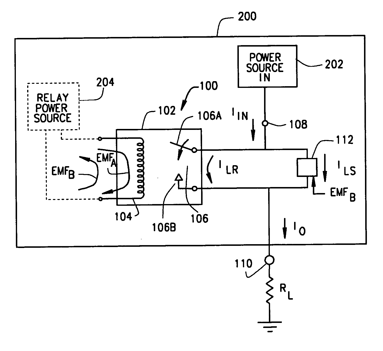
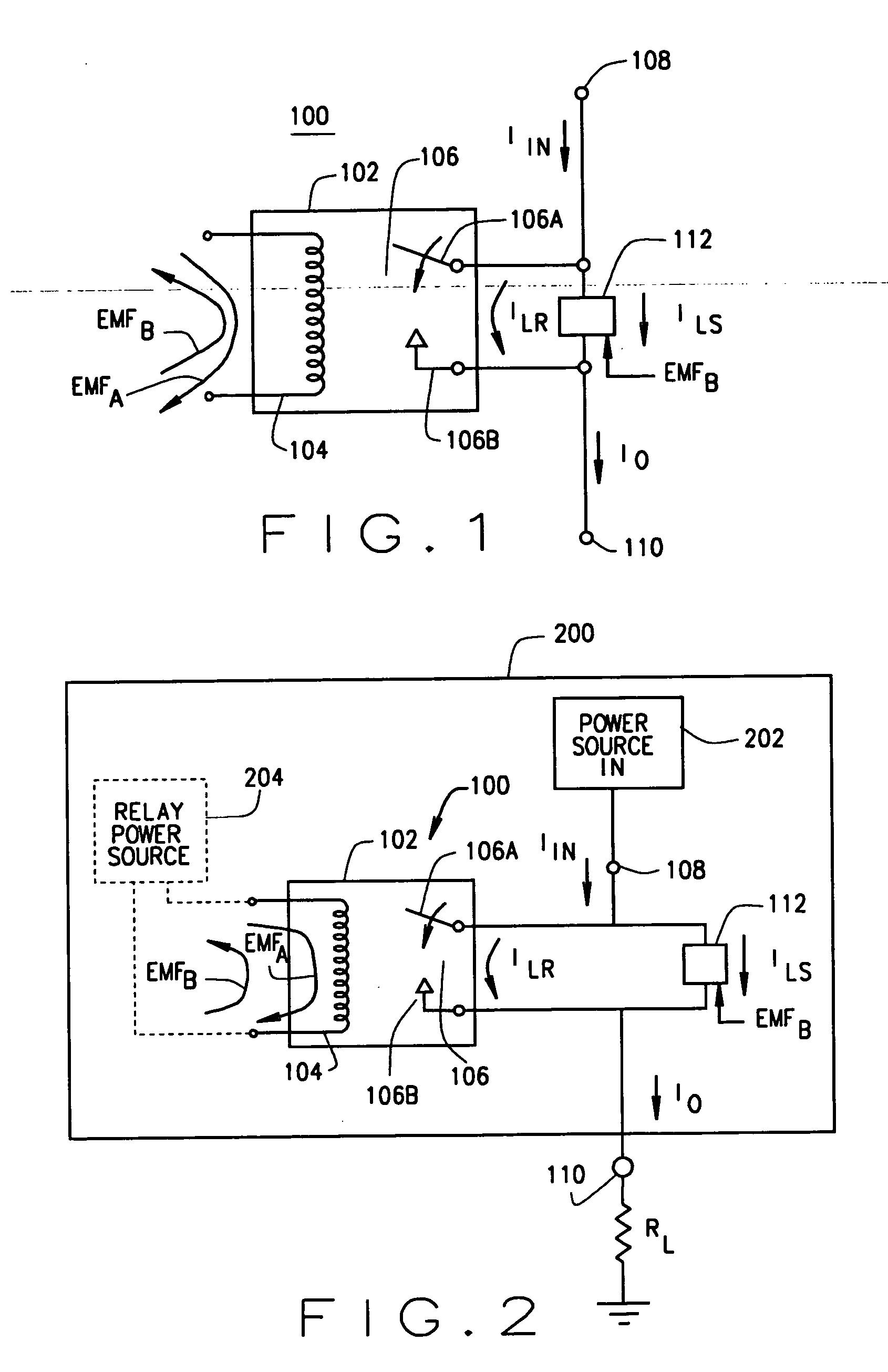
[0019] In one embodiment of the invention, an arc suppression circuit for a power circuit or power supply includes a relay having a coil and a set of contacts for providing a portion of an input power as load power to an output. The relay coil is configured for closing the relay contacts in response to receiving relay activating energy and for generating back EMF energy following termination of the receiving of the relay activating energy. A switch is connected in parallel to the relay contacts and is configured for providing a portion of the input power as supplemental load power to the output as a function of back EMF energy.

[0020] Referring to FIG. 1, one exemplary embodiment of an arc suppression circuit 100 is illustrated. An electromechanical relay 102 includes a relay coil 104 that operates to open and close the relay contacts 106 (shown...


PUM


Abstract

An arc suppression circuit for a power switch or power supply with a relay having a coil and a set of contacts for providing a portion of an input power as load power to an output. The relay coil is configured for closing the relay contacts in response to receiving relay activating energy and for generating back EMF energy following termination of the receiving of the relay activating energy. A switch is connected in parallel to the relay contacts and is configured for providing a portion of the input power as supplemental load power to the output as a function of back EMF energy. Also, a method of suppressing damaging arcing across relay contacts in a power switch or power supply includes receiving back EMF energy generated by the relay coil following termination of the relay coil receiving activating energy and connecting supplemental load power to the output in parallel with the relay contacts in response to the receiving of the back EMF energy.

Description

FIELD OF THE INVENTION [0001] The present invention relates to a circuit for use in a power supply and, more specifically, relates to a circuit or power supply capable of having reduced harmful arcing across contacts of a relay providing output power. BACKGROUND OF THE INVENTION [0002] Power supplies often utilize relays for switching on and off power provided to an output of the power supply and therefore to a load. Relays are used due to the low resistance and therefore power dissipation of the relay contacts as compared to alternative switching devices, such as solid state relays, that have significantly higher voltage drops across the closed switch. However, the mechanical relays often degrade, at least in part, due to harmful arcing across the relay contacts that result from the relay contacts being powered before and after the opening and closing. Arcing often occurs across the relay contacts during the closing of the contacts, but prior to the relay contacts making physical c...

Claims


Application Information

Patent Timeline
Patent Type & Authority Applications(United States)
IPC IPC(8): H02H3/00
CPCH01H50/541H01H9/30
Inventor NESS, KEITH DOUGLAS
Owner WATLOW ELECTRIC MFG
Why Eureka
Try Eureka