Lightweight direct methanol fuel cell and supporting systems

a fuel cell and direct methanol technology, applied in the field of fuel cells, can solve the problems of high cost of liquefying hydrogen at cryogenic temperatures, large insulated containers for storing liquefied hydrogen, and relatively high cost of compressing and storing hydrogen gas

Inactive Publication Date: 2007-01-18
CREARE INC
View PDF7 Cites 43 Cited by
  • Summary
  • Abstract
  • Description
  • Claims
  • Application Information

AI Technical Summary

Benefits of technology

[0014] In yet another aspect, the present invention is directed to a fuel cell system that has a fluid inventory and utilizes a recirculated fluid having a temperature. The fuel cell system comprises at least one anode flow field for conducting the recirculated fluid and a fluid inventory control system. The fluid inventory control system comprises a sensor for measuring the fluid inventory. The sensor generates a first control signal. A first flowpath extends from the at least one anode flow field to the sensor. At least one second flowpath is in fluid communication with the first flowpath and extends from the sensor to the first anode flow field. A device is operatively coupled to the sensor for controlling the temperature of the recirculated fluid in response to the first signal.

Problems solved by technology

Liquefying hydrogen at cryogenic temperatures is an expensive process, and storing liquefied hydrogen requires bulky insulated containers that vent and lose hydrogen due to heat leaks.
Similarly, compressing and storing hydrogen gas is relatively costly, and storing this highly flammable gas is more problematic than storing liquid methanol.

Method used


Image

  • Lightweight direct methanol fuel cell and supporting systems
  • Lightweight direct methanol fuel cell and supporting systems
  • Lightweight direct methanol fuel cell and supporting systems

Examples


Embodiment Construction

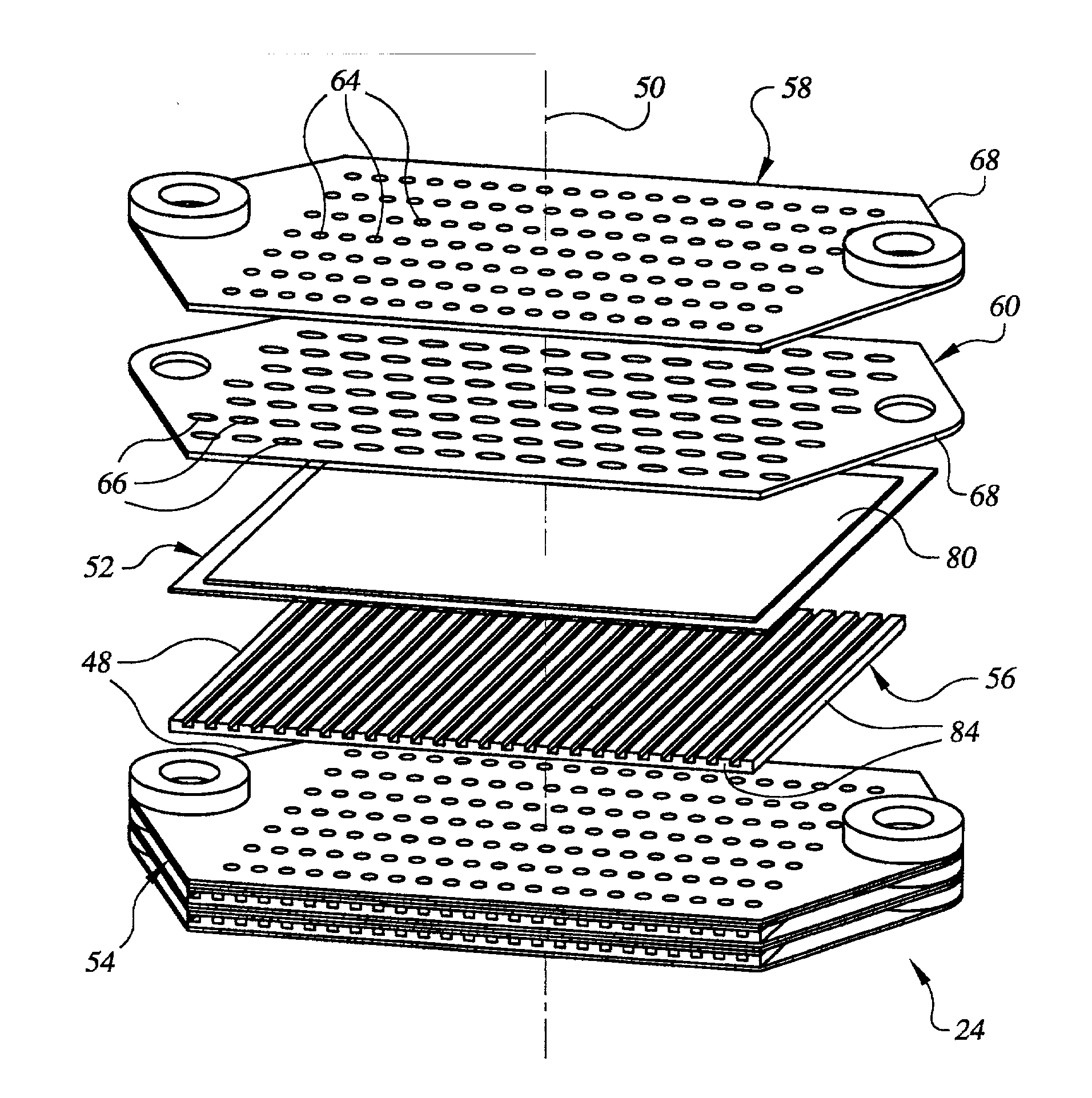
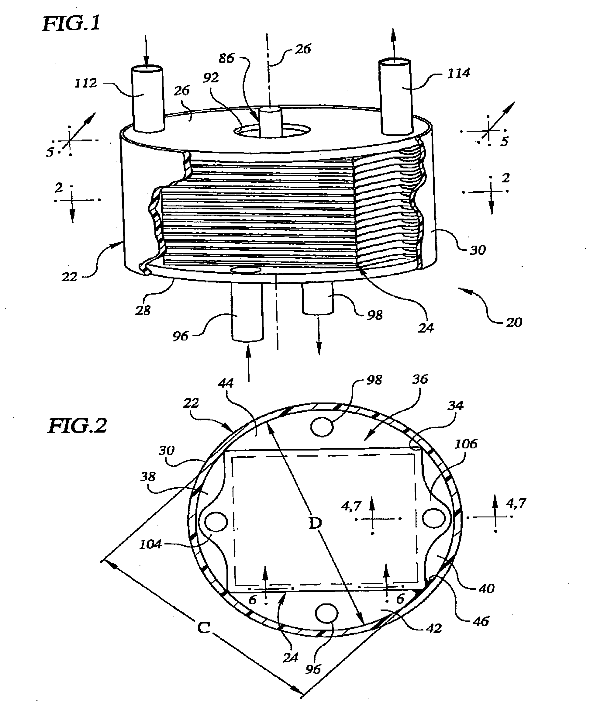
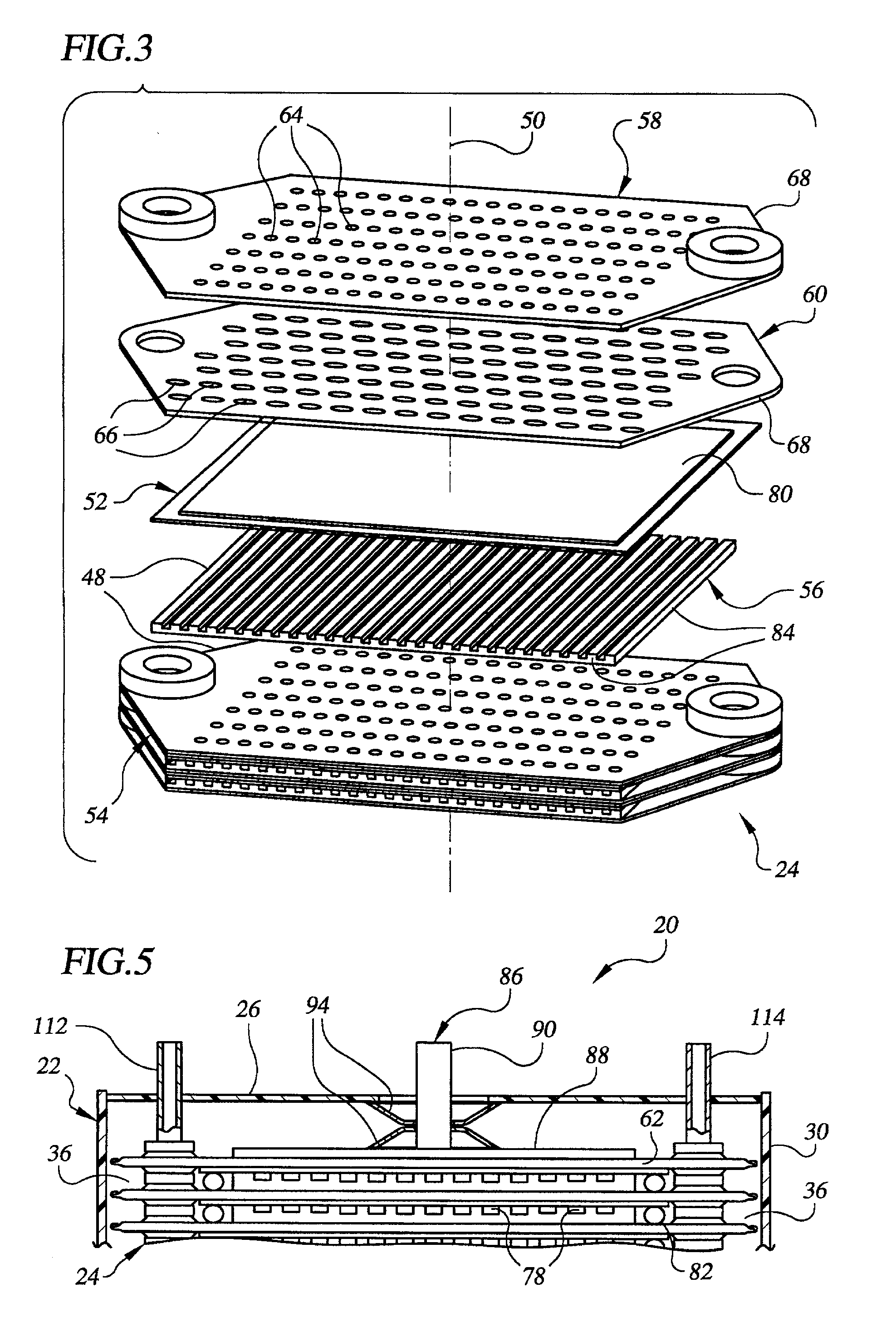
[0031] Referring now to the drawings, wherein like numerals indicate like elements, FIG. 1 illustrates in accordance with the present invention a fuel cell unit, which is generally denoted by the numeral 20. As will become apparent from the accompanying drawings and corresponding description, fuel cell unit 20, alone and in conjunction with the various supporting systems described below, contains a number of innovative features that can result in reduced size, weight, cost, and complexity of the fuel cell unit and the supporting systems when compared to conventional fuel cell systems having comparable power outputs. Such reductions are important in developing practical fuel cell units and supporting systems. These reductions are a result of a number of factors, including innovative choice of materials for, and design of, the various components of fuel cell 20 unit and supporting systems and innovative approaches to supporting the operation of the fuel cell unit.

[0032] As shown in F...


PUM

PropertyMeasurementUnit
thicknessaaaaaaaaaa
widthaaaaaaaaaa
lengthaaaaaaaaaa

Abstract

A lightweight direct methanol fuel cell unit (20) comprising a fuel cell stack (24) enclosed within a housing (22). In one embodiment the fuel cell stack includes a plurality of polymer electrolyte membrane electrode assemblies (52) stacked alternatingly with a plurality of bipolar plates (48). Each bipolar plate includes a cathode flow field (78) defined by a porous cathode flow field structure (56) and an anode flow field (62) defined by an upper plate (58) and a lower plate (60) separated from one another by a plurality of spacers (64). The anode flow fields are manifolded with one another via manifold embossments (118, 120) that are hermetically sealed with one another with a gasket (126). The fuel cell stack and housing are shaped so as to form four manifold regions (36) in the spaces between the fuel cell stack and housing. The fuel cell stack is compressed within the housing by compression members (94) located between the fuel cell stack and housing so as to place the sidewall (30) of the housing into tension. Supporting systems for the fuel cell unit include a fuel handling system (502), an oxidant handling system (600), and a liquid inventory control system (700).

Description

RELATED APPLICATION DATA [0001] This application claims the benefit of priority of U.S. Provisional Patent Application No. 60 / 276,314, filed Mar. 16, 2001, entitled “Compact, Lightweight Direct Methanol Fuel Cell.”STATEMENT OF GOVERNMENT RIGHTS [0002] This invention was made with Government support under contract MDA972-01-C-0070 awarded by the Defense Advanced Research Project Agency. The Government has certain rights in the invention.FIELD OF THE INVENTION [0003] The present invention is generally related to the field of fuel cells. More particularly, the present invention is directed to a lightweight fuel cell stack and supporting systems therefor. BACKGROUND OF THE INVENTION [0004] A fuel cell electrochemically converts a fuel and an oxidant into direct current electricity that may be used to power any of a variety of electrical devices, such as electromechanical equipment, e.g., motors and actuators, digital and analog circuits, e.g., microprocessors and radio transmitters, and...

Claims


Application Information

Patent Timeline
Patent Type & Authority Applications(United States)
IPC IPC(8): H01M8/02H01M8/10H01M8/04H01M8/06H01M8/24
CPCH01M8/0206Y02E60/523H01M8/0232H01M8/0234H01M8/025H01M8/0258H01M8/0267H01M8/0271H01M8/0278H01M8/0286H01M8/0297H01M8/04007H01M8/04097H01M8/04119H01M8/04171H01M8/04186H01M8/04208H01M8/04291H01M8/0662H01M8/1009H01M8/1011H01M8/246H01M8/247H01M8/2475H01M8/248H01M8/0228Y02E60/50H01M8/2483H01M8/241H01M8/2484H01M8/0276
Inventor IZENSON, MICHAEL G.CROWLEY, CHRISTOPHER J.AFFLECK, WAYDE H.
Owner CREARE INC
Why Eureka
Try Eureka