

Guided vehicle system and travel route map creation method for guided vehicle system
- Summary
- Abstract
- Description
- Claims
- Application Information
AI Technical Summary
Benefits of technology
Problems solved by technology
Method used
Image

Examples
Example
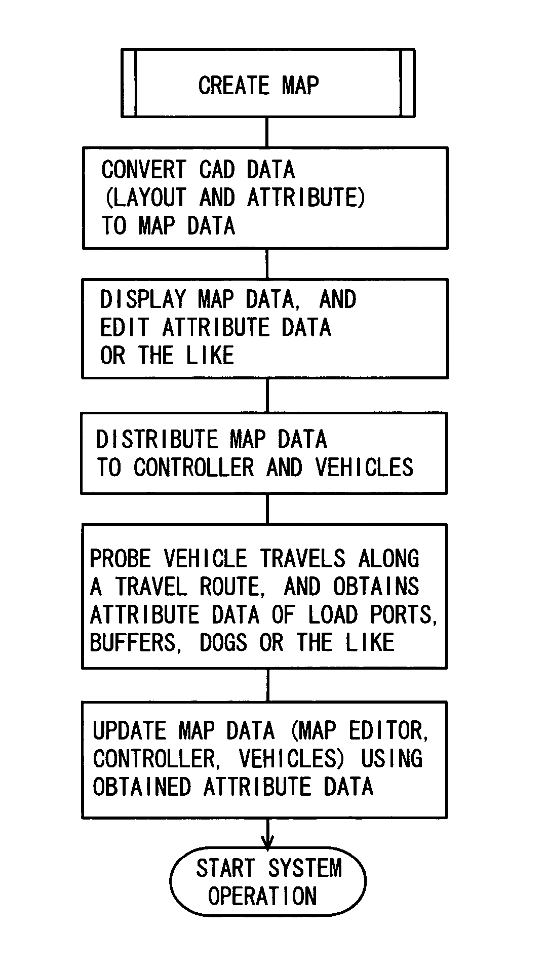
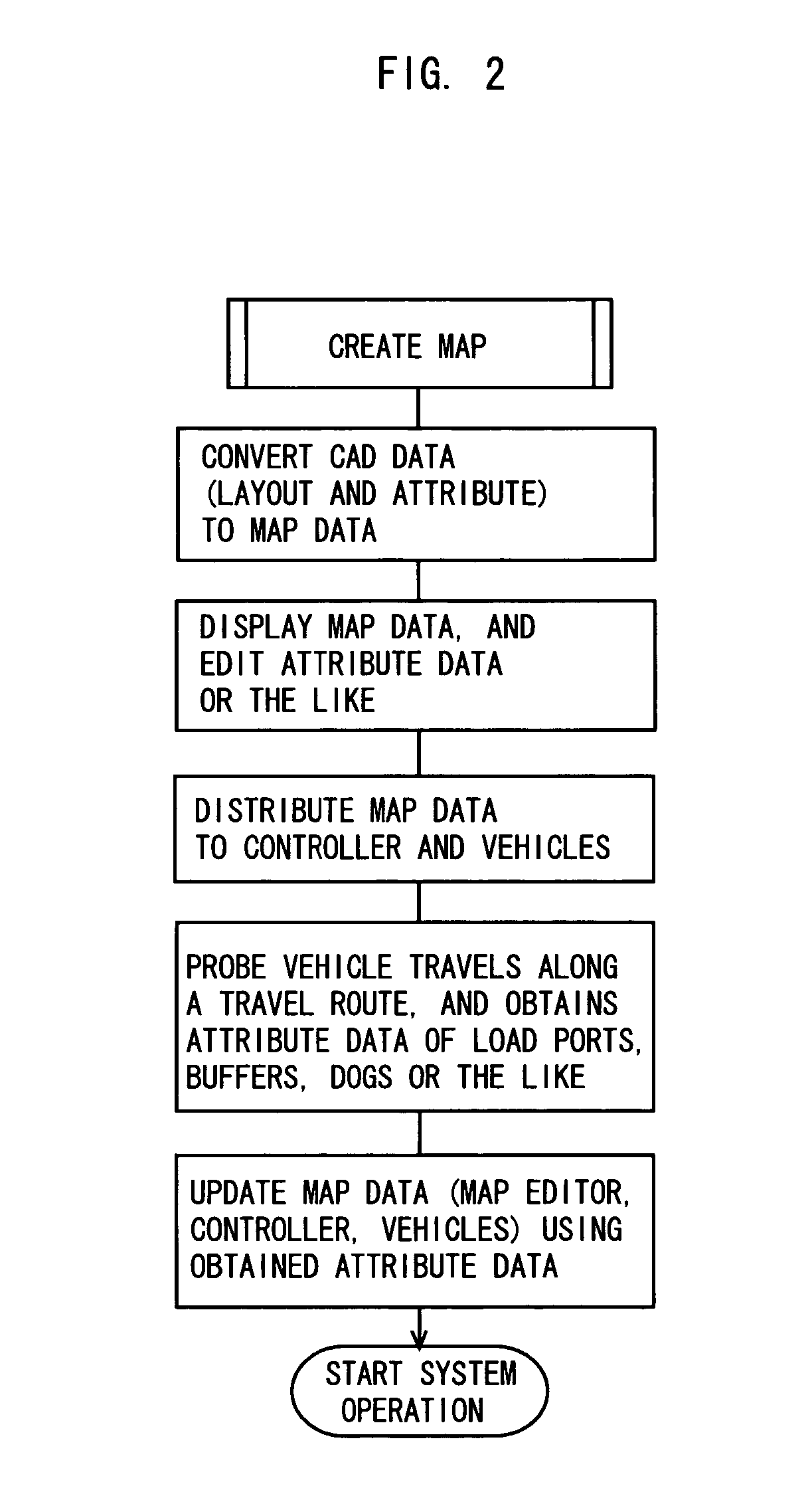
[0036] Hereinafter, an embodiment in the most preferred form for carrying out the present invention will be described.
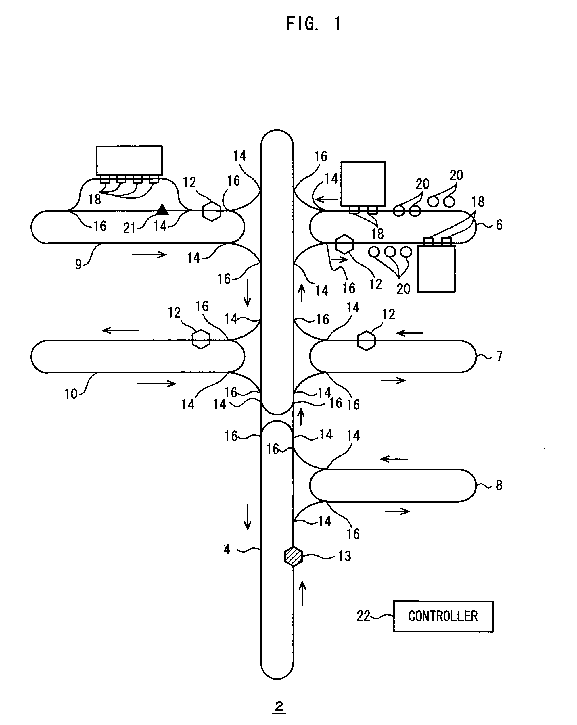
[0037] FIGS. 1 to 5 show a guided vehicle system 2 according to the embodiment. Though the embodiment will be described taking a system of overhead traveling vehicles as an example, the present invention is applicable to a system of rail vehicles on the ground, and a system of automated non-rail guided vehicles on the ground. The guided vehicle system 2 includes travel routes such as an inter-bay route 4 as a main route and intra-bay routes 6 to 10 provided for respective bays. For example, more than one hundred overhead traveling vehicles 12 travel on the travel routes.
[0038] A reference numeral 13 denotes a probe vehicle. For example, one vehicle selected from the overhead traveling vehicles 12 is used as the probe vehicle 13. The probe vehicle 13 is equipped with a sensor for verifying positions of load ports (stations for transfer of articles) 18 and buffers20 ...
PUM
 Abstract
Description
Claims
Application Information