
Multifunctional bioimplantable structure and method of preparing the same

Active Publication Date: 2018-10-11
RES & BUSINESS FOUNDATION SUNGKYUNKWAN UNIV +1
View PDF0 Cites 0 Cited by
  • Summary
  • Abstract
  • Description
  • Claims
  • Application Information

AI Technical Summary

Benefits of technology

The present invention provides a structure that can reliably load drugs, control the release of the drugs, and inhibit cell proliferation. The structure has a polymer layer with a large surface area and a nano-turf structure for easy loading of drugs. The amount of drugs that can be loaded can be controlled, and personalized release can also be achieved. The metal layer works as a passivation layer for easy loading of drugs into the polymer layer, and the release of drugs can be controlled quantitatively by applying near infrared rays to increase the temperature of the metal layer. The polymer layer can be easily coated onto a flexible and curved base using the dip coating method.

Problems solved by technology

Thus, the method may be complicated.

Method used


Image

  • Multifunctional bioimplantable structure and method of preparing the same
  • Multifunctional bioimplantable structure and method of preparing the same
  • Multifunctional bioimplantable structure and method of preparing the same

Examples


example 2

[0085]The experiment was conducted again using the same producing method as the producing method as described in the above-mentioned first example. However, in this example, an UV exposure time is different from an reactive ion etching (RIE) time. When the RIE time is constantly controlled, the SEM image of the formed stent is shown in FIG. 5(a). When the UV exposure time is constantly controlled, the SEM image of the formed stent is shown in FIG. 5(b).

[0086]As shown in FIG. 5(a) and FIG. 5(b), it was confirmed that the thickness and depth of the nanostructure or pores may be easily controlled.

example 3

[0087]In order to confirm the wettability of the structure, additional experiments were conducted while controlling the plasma time. The result graph is shown in FIG. 6. As shown in FIG. 6, it was confirmed that as the depth of the polymer layer becomes deeper, the surface of the structure is more hydrophilic.

[0088]It is also known that the greater the wettability of the structure on the cells, the better the adhesion of the structure to the cell. As shown in FIG. 6, the contact angle (CA) of the glass was similar to the CA of a surface of the structure as has been RIE-treated at 21° C. for about 300 seconds. However, in spite of the similar CAs, the cell adhesion differs between the glass and the present structure. From this, it is possibly confirmed that the cell adhesion control factor is not only the wettability but also the cell adhesion is controlled by the polymer layer itself.

example 4

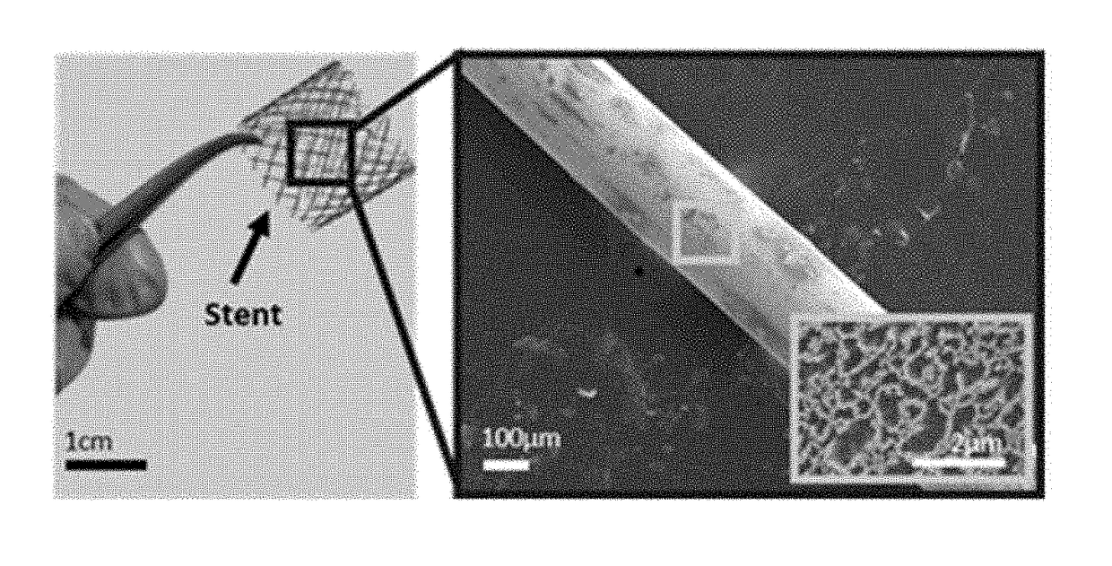
[0089]For loading the drug, the stent produced in the Example 1 was immersed in the drug containing solution, to load the drug into the pores formed in the polymer layer. In this connection, the drug was Doxorubicin. The SEM images of the stent with nano-sized pores, the drug-loaded stent, and the drug-releasing stent are shown in FIG. 7.

[0090]As shown in FIG. 7, the drug in a form of nanoparticles dispersed in water was loaded and diffused without a further surface treatment.


PUM

PropertyMeasurementUnit
Temperatureaaaaaaaaaa
Structureaaaaaaaaaa
Biocompatibilityaaaaaaaaaa

Abstract

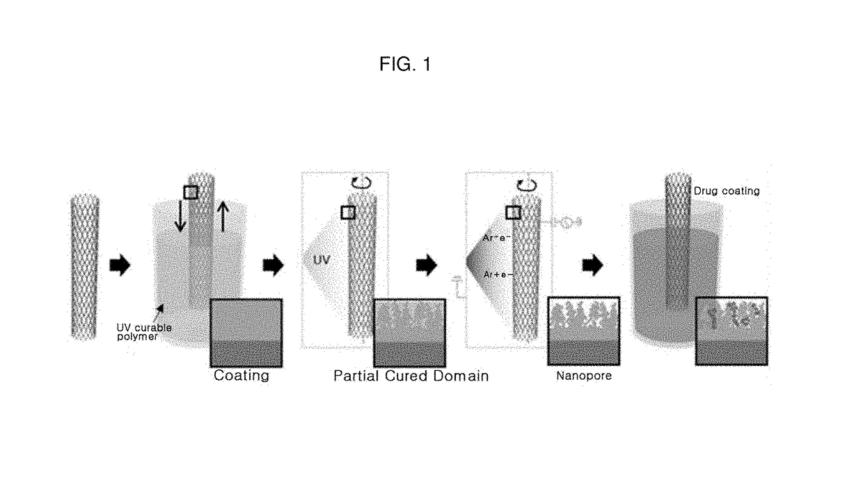
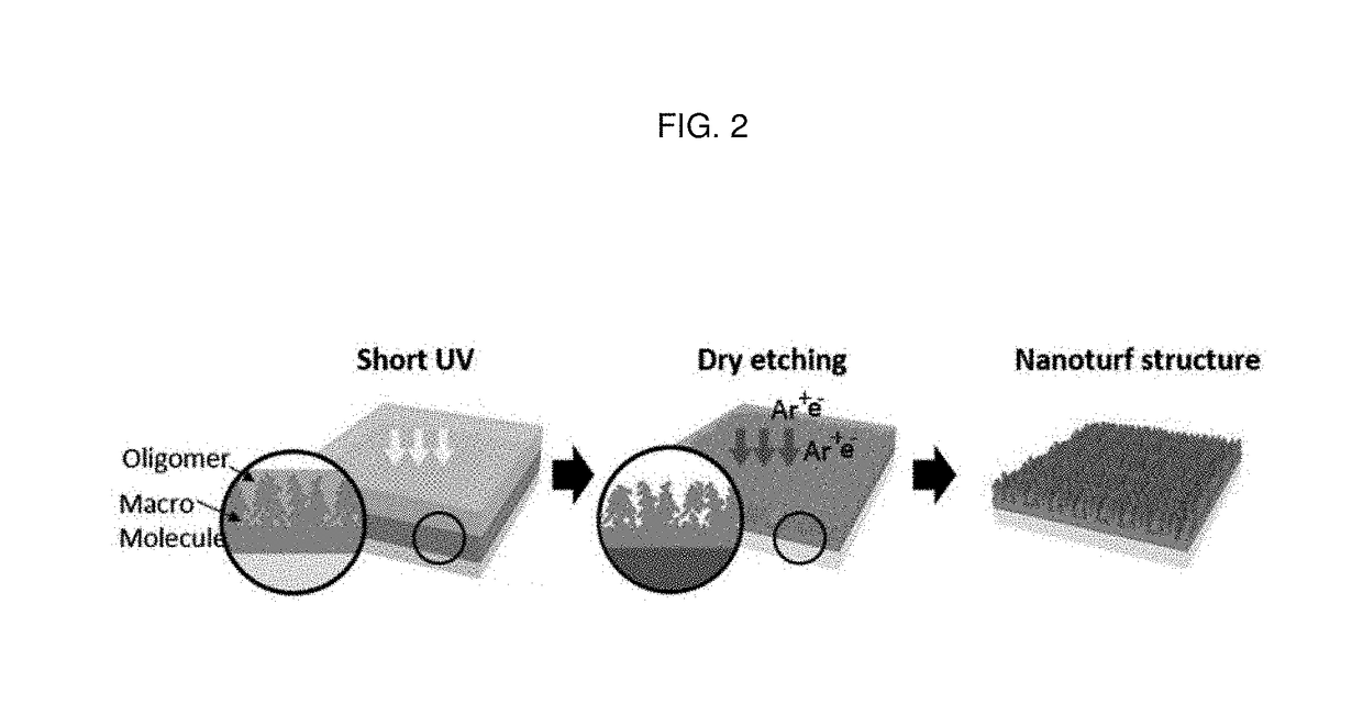
The present disclosure provides a method for producing a multifunctional transplantable structure, the method having: preparing a transplantable base; coating a polymer layer on the base, wherein the polymer layer is partially curable; curing the polymer layer such that the polymer layer has cured and non-cured portions; and dry-etching the polymer layer to remove the non-cured portion thereof, to allow the polymer layer to have a nano-turf structure having pores defined therein.

Description

CROSS-REFERENCE TO RELATED APPLICATION[0001]This application claims the benefit of Korean patent application No. 10-2017-0044570 filed on Apr. 6, 2017, the entire content of which is incorporated herein by reference for all purposes as if fully set forth herein.FIELD OF INVENTION[0002]The present disclosure relates to a transplantable structure and a method for producing the same. More particularly, the present disclosure relates to a multifunctional transplantable structure having excellent drug loading ability and capable of selective release of loaded drug therein, and a method for producing the structure.BACKGROUND OF INVENTION[0003]Biocompatible nano-surface modification techniques applied to transplantable devices to enhance biocompatibility of a material by controlling reaction between cells and an interface of the material that directly or indirectly affect the cells or tissues are increasingly being studied[0004]Conventional biocompatible nano-surface modification technique...

Claims


Application Information

Patent Timeline
IPC IPC(8): A61F2/90A61L31/10A61L31/14A61L31/16A61L31/08A61L31/02A61K31/704
CPCA61F2/90A61L31/10A61L31/146A61L31/16A61L31/088A61L31/148A61L31/022A61K31/704A61F2250/0067A61F2240/001A61L2420/08B05D1/18B05D3/107B05D3/067A61F2250/0068B05D3/12A61K9/0097A61K9/0009A61K9/0024A61K47/32A61K47/34A61L27/306A61L27/34A61L27/54
Inventor KIMLEE, SO RILEE, JI YEONHWANG, GYO YEON
Owner RES & BUSINESS FOUNDATION SUNGKYUNKWAN UNIV
Learn More