Device and method for the production of multi-arched structural components from a fiber composite

Active Publication Date: 2013-01-24
AIRBUS OPERATIONS GMBH
View PDF5 Cites 5 Cited by
  • Summary
  • Abstract
  • Description
  • Claims
  • Application Information

AI Technical Summary

Benefits of technology

[0026]In this manner the jig can easily be manually loaded w

Problems solved by technology

During separation of the laminating bonding device from the jig, as a result of the curvature of the structural component in conjunction with the stringers that extend longitudinally on the inside, so-called undercut problems occur relative to the associated receiving channels on the jig, which problems, depending on the degree of curvature of the structural component, might impede demolding as a result of a positive-locking fit that constitutes a hindrance.
However, this is associated with a disadvantage in that the degree of curvature of the structural component is severely limited by the feasibility of demolding as a result of the undercut problem.
As a result of the undercut problem, in conventional j

Method used


Image

  • Device and method for the production of multi-arched structural components from a fiber composite
  • Device and method for the production of multi-arched structural components from a fiber composite
  • Device and method for the production of multi-arched structural components from a fiber composite

Examples


Example

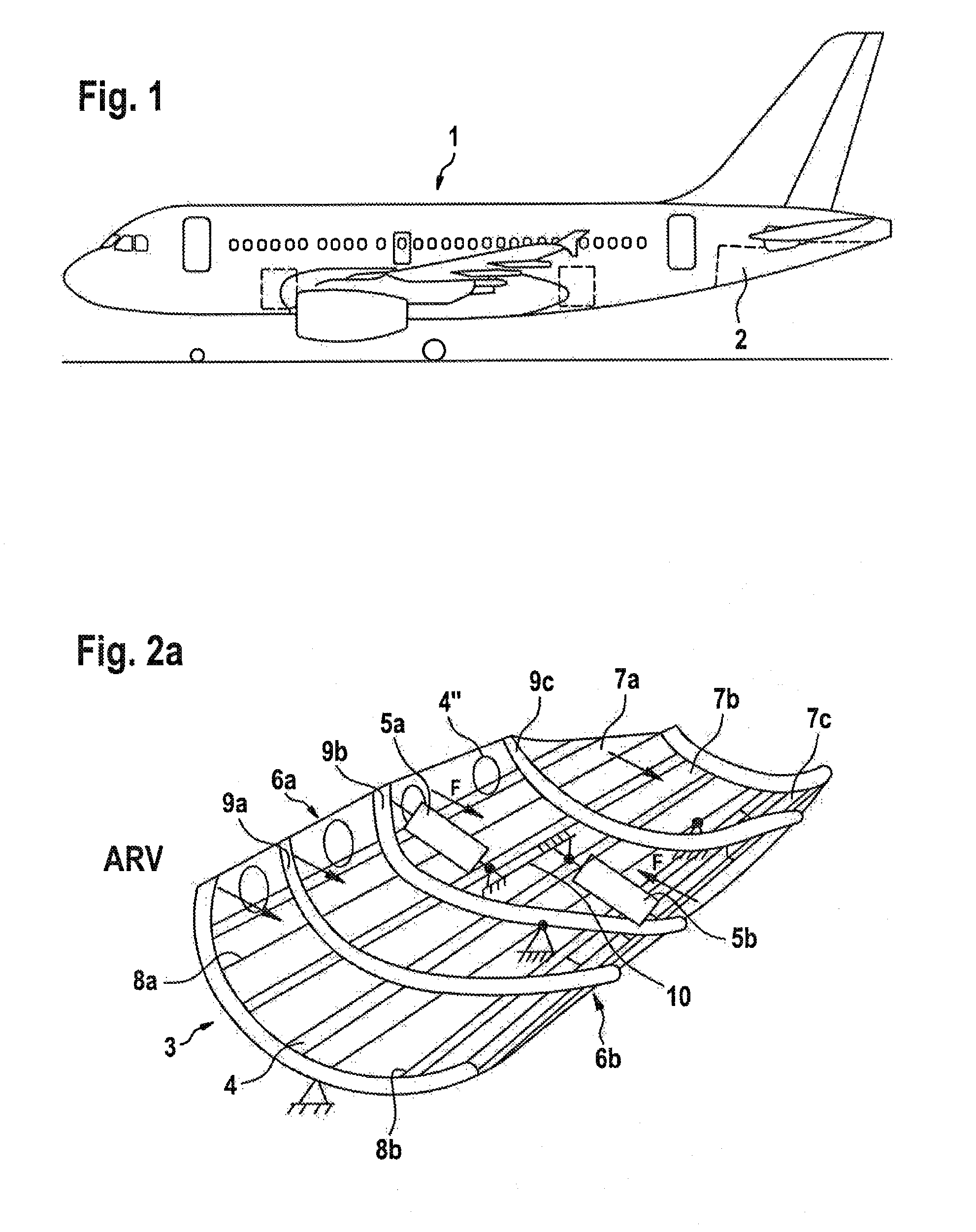
[0036]According to FIG. 1 the commercial aircraft shown comprises a wide-body fuselage which, produced in a shell construction, also comprises a rear three-dimensional, arched fuselage shell 2.

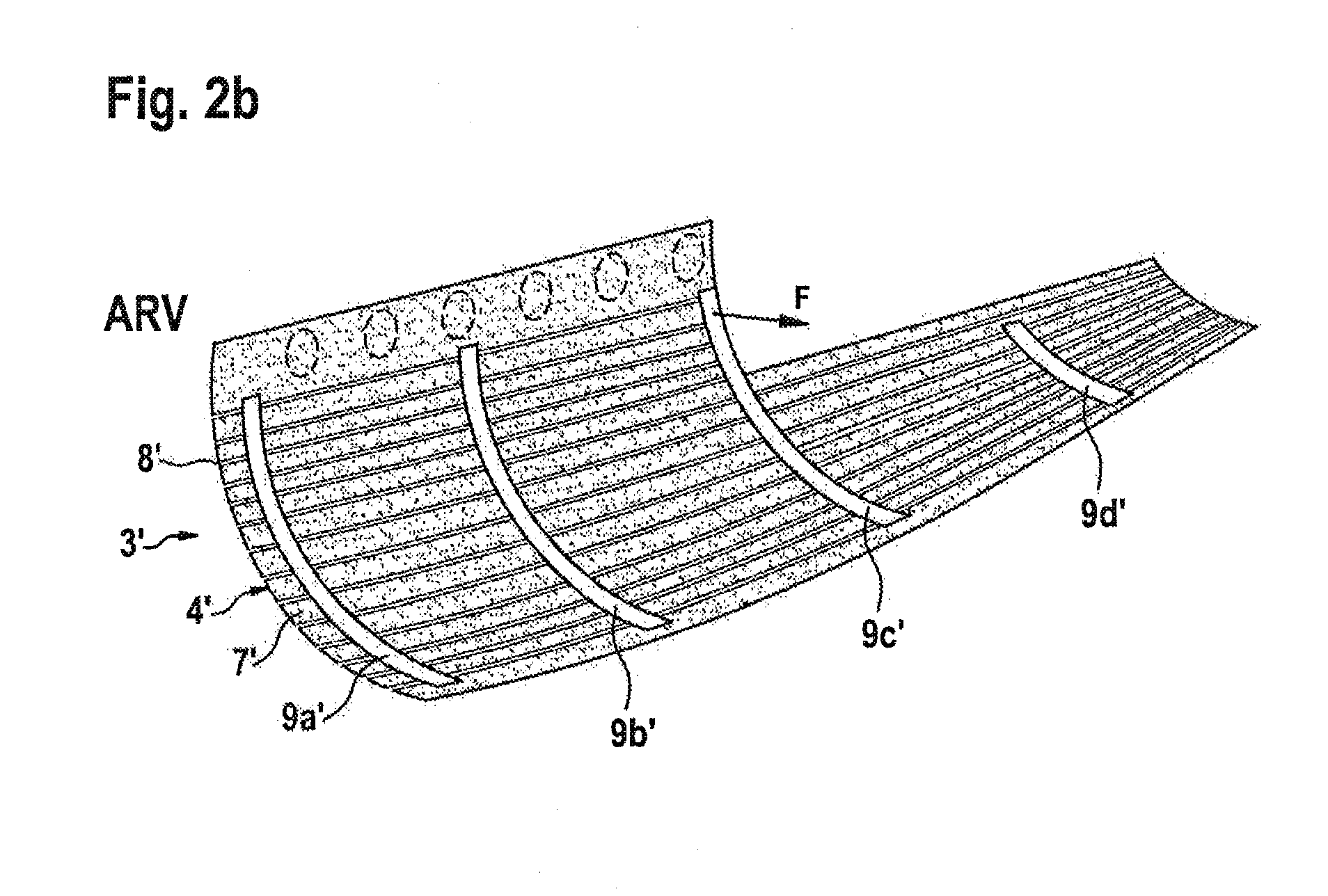
[0037]This structural component is made by means of a jig according to FIG. 2a that comprises an outwards-arched mounting surface 3. On the outside a plurality of receiving channels 4 arranged spaced apart from each other extend over the mounting surface 3 for inserting stringers as construction components, with the aforesaid together with the auxiliary materials to be applied to the mounting surface 3 at the end of the production process forming the three-dimensionally arched structural component.

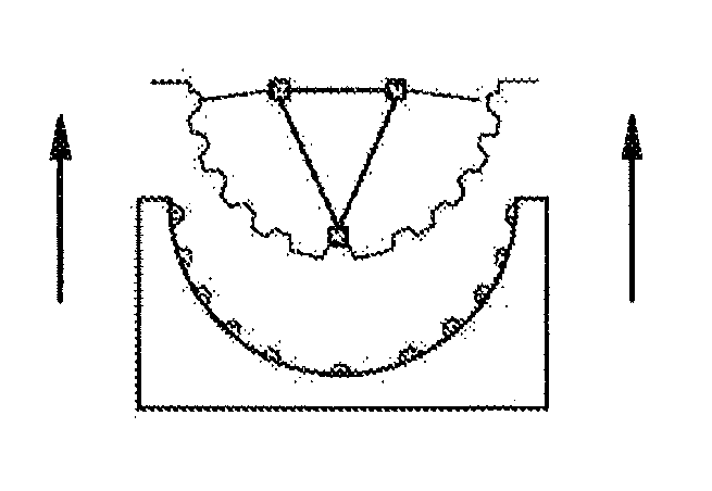
[0038]The outwards-arched mounting surface 3, in the diagram arranged underneath the shown jig, at the edge can be elastically deformed inwards, as indicated by the two opposing rows of arrows. For this purpose a plurality of actuators 5a, 5b that are articulated to the inside are provided (as an exa...


PUM

PropertyMeasurementUnit
Forceaaaaaaaaaa
Elasticityaaaaaaaaaa

Abstract

A device for the production of structural components from a fiber composite material, the components being three-dimensionally arched over a large surface, including a jig having a convex mounting surface having receiving channels for the insertion of structural components, wherein the loaded jig interacts with a laminating bonding device having a corresponding shape for forming the structural component under pressure, wherein the mounting surface includes a plurality of individually elastically deformable mounting shell parts arranged adjacent to each other along at least one longitudinally extending pitch line and attached to a plurality of elastically deformable supporting frame elements extending on the interior of the shell at a right angle to the pitch line, and a plurality of actuators for deforming the mounting surface between an extended position (A) and at least one retracted position (B) to move the jig from the bonding device relative to the receiving channels without undercuts.

Description

CROSS-REFERENCE TO RELATED APPLICATIONS[0001]The present application is a continuation of International Application No. PCT / EP2011 / 054717, filed Mar. 28, 2011, published in German, which claims priority from U.S. Provisional Patent Application No. 61 / 318,920, filed on Mar. 30, 2010, and German Patent Application No. 10 2010 013 478.3, filed on Mar. 30, 2010, the disclosures of which are incorporated herein by reference.TECHNICAL FIELD[0002]The present invention relates to a device and a method for the production of in particular doubly arched large-area structural components from a fiber composite material, comprising a jig having a corresponding convex mounting surface which has receiving channels, which are spaced apart from each other and extend at least in longitudinal direction, for the insertion of construction components, in particular stringers, and which can be loaded with auxiliary materials, wherein the loaded jig interacts with a laminating bonding device having a corres...

Claims


Application Information

Patent Timeline
IPC IPC(8): B32B37/00B32B38/00
CPCB29C31/008B29C31/085B29C33/485Y10T156/17B29L2031/3082Y02T50/433Y10T156/1002B29C70/462Y02T50/40
Inventor LONSDORFER, GEORGWACHENDORF, ADRIANHINZ, REMODESCHAUER, NIELSANDRA, ADAM
Owner AIRBUS OPERATIONS GMBH
Why Eureka
Try Eureka