Folding trailer

Active Publication Date: 2018-09-25
DAVIS RUSSELL T
View PDF21 Cites 3 Cited by
  • Summary
  • Abstract
  • Description
  • Claims
  • Application Information

AI Technical Summary

Benefits of technology

[0013]The trailer of this invention tilts toward the rear with the entire bed forming a ramp for easy loading (and unloading) when the airbags are

Problems solved by technology

Flat bed trailers are relatively bulky and take up considerable storage space when not in use, when on display at retail stores, and when shipped from the point of manufacture to the point of sale.
Howe

Method used


Image

  • Folding trailer
  • Folding trailer
  • Folding trailer

Examples


Embodiment Construction

[0032]1. The Invention in General

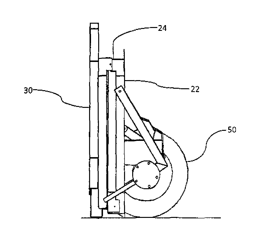
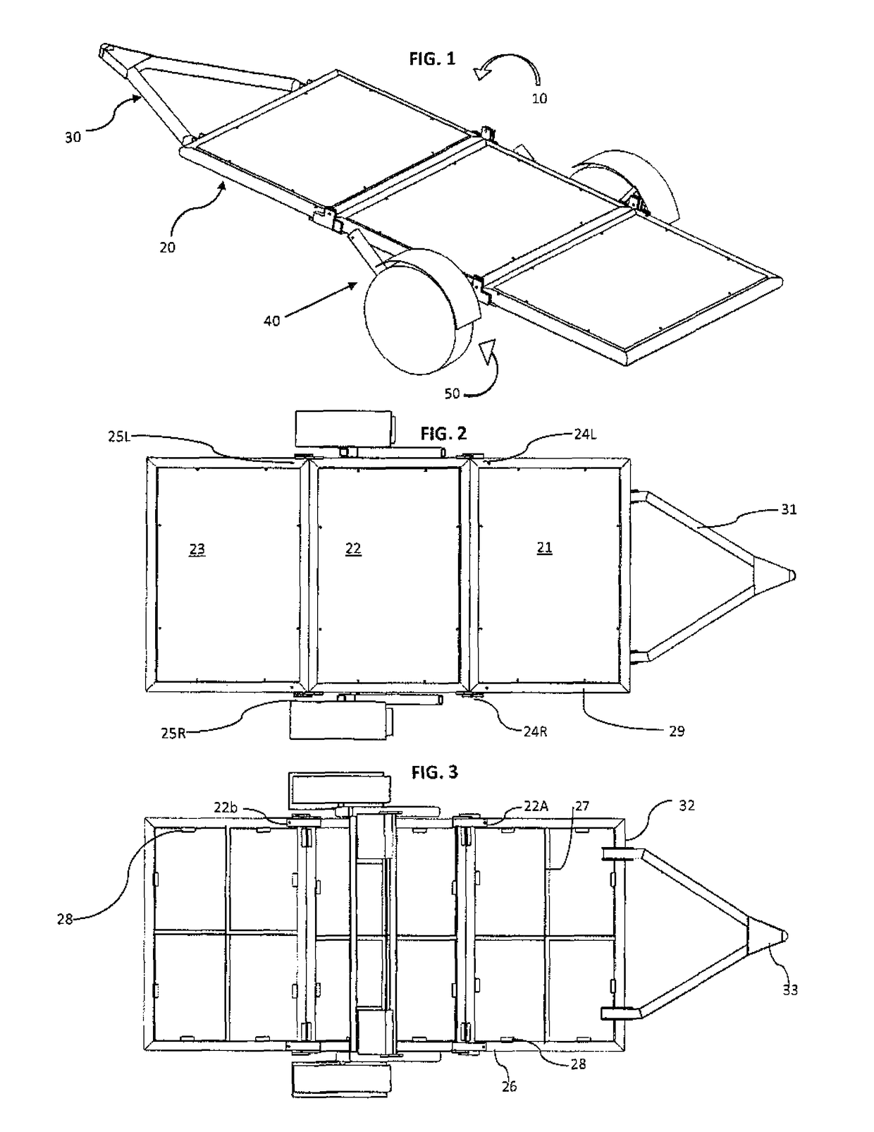
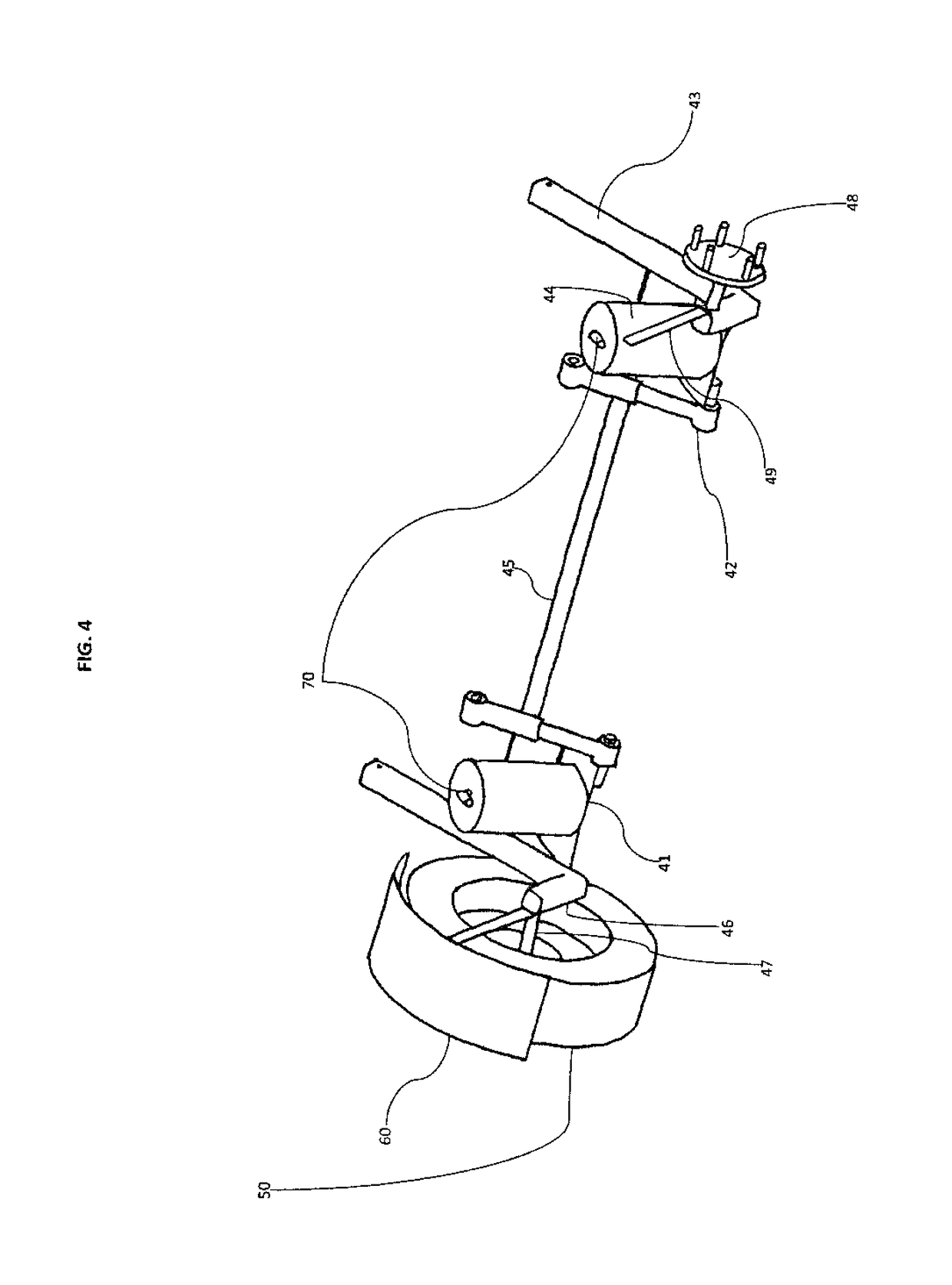
[0033]This invention is best understood by reference to the drawings. Referring first to FIGS. 1 to 3, a preferred embodiment of the trailer 10 of this invention comprises a flat bed 20 with two sides, a tongue 30, a suspension system 40 with two sides, and a wheel 50 attached to each side of the suspension system. The components are discussed in more detail below.

[0034]2. The Flat Bed

[0035]The flat bed 20 comprises three sections—a front section 21, a middle section 22, and a rear section 23. The front section is connected to the middle section by a first hinge. The term “hinge” is used herein to refer to a single integral hinge (such as a piano hinge) and to multiple hinges that act along a common axis (such as door hinges). In the embodiment shown, the first hinge consists of two separate hinges—hinge 24R on the right side and hinge 24L the left side. The middle section is connected to the rear section by a second hinge. In the embodiment shown, t...


PUM


Abstract

A trailer has a three-section flat bed in which the front and rear sections fold onto the middle section. The trailer has an airbag suspension system and one wheel on each side. When the airbags are deflated, the entire flat bed forms a ramp for loading and unloading. When the airbags are deflated and the flat bed is folded, the trailer can be stored vertically while resting on its wheels.

Description

CROSS-REFERENCE TO RELATED APPLICATIONS[0001]This application is a continuation in part of U.S. application Ser. No. 14 / 645,664, Mar. 12, 2015, now pending, which application is a continuation in part of U.S. application Ser. No. 14 / 146,829, Jan. 3, 2014, which application claims the benefit of U.S. Provisional Application Ser. No. 61 / 749,522, Jan. 7, 2013.FIELD OF THE INVENTION[0002]This invention relates to land vehicles. More particularly, this invention relates to trailers.BACKGROUND OF THE INVENTION[0003]A trailer is an unpowered wheeled vehicle that is used for hauling cargo. The surface upon which the cargo rests is most commonly known as a bed, but is also known as a deck or a platform. Trailers having an uncovered flat bed are used to transport motorcycles, lawn tractors, all terrain vehicles, watercraft, and other personal cargo. Flat bed trailers typically contain tongues with couplers that attach to a trailer hitch mounted on the back end of an automobile or truck.[0004]...

Claims


Application Information

Patent Timeline
IPC IPC(8): B60D1/06B60D1/46B60P1/16B62D63/06B60G11/27
CPCB62D63/061B60D1/46B60P1/16B62D63/062B60G11/27B60D1/06B60G2202/152B60G2300/04B60P1/18B60P1/433
Inventor DAVIS, RUSSELL T.
Owner DAVIS RUSSELL T
Why Eureka
Try Eureka